ESP32 with TTL-RS485 serial connection with Solis S6-EH3P8K-H inverter

Hi,

I have been setting up a configuration where I should read information from my Solis inverter by using its RS485 connector.

I’m using a ESP32 38 pin developer board. And a TTL-RS485 converter: https://nl.aliexpress.com/item/32853794532.html#nav-specification

You can find the register map “RS485_MODBUS RTU Hybrid Inverter Protocol” of my Solis inverter here.

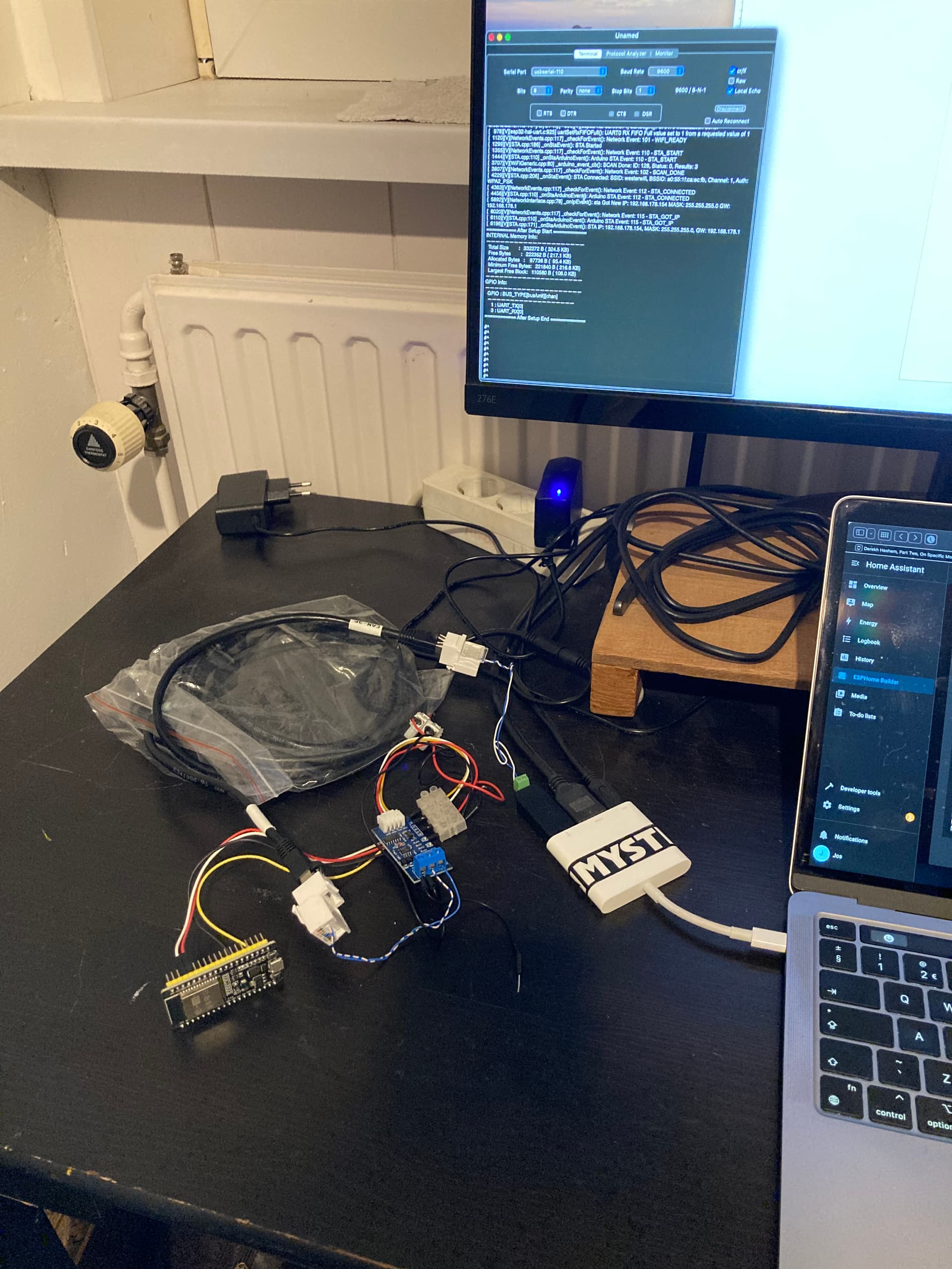
But I don’t see any information from my Solis inverter in the HA ESPhome log.
I think my ESP32 with RS485 converter doesn’t work well.

Here’s my wiring:

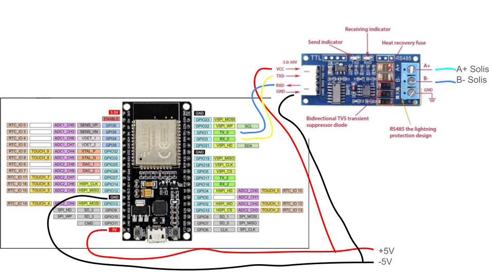
(Note that TX and RX inbetween are crossed.)

And here’s my yaml code:

esphome:
  name: meterkast
  friendly_name: meterkast

esp32:
  board: esp32dev
  framework:
    type: arduino

# Enable logging
logger:
  baud_rate: 0
  level: VERBOSE

# Enable Home Assistant API
api:
  encryption:
    key: "UTTPgM3Yrv0BinFBh/KFIQeqUt19xxxxxxxxy4="

ota:
  - platform: esphome
    password: "17200cbb9881dxxxxxxxxxxxx"

wifi:
  ssid: !secret wifi_ssid
  password: !secret wifi_password

  # Enable fallback hotspot (captive portal) in case wifi connection fails
  ap:
    ssid: "Meterkast Fallback Hotspot"
    password: "QAxxxxxxxxxxxxx"

captive_portal:

uart:
  id: uart_1
  tx_pin: GPIO1
  rx_pin: GPIO3
  baud_rate: 9600
  parity: NONE
  stop_bits: 1
  data_bits: 8
  debug:
    direction: BOTH

modbus:
  id: modbus1
  uart_id: uart_1
  send_wait_time: 320ms
  ## role: server

modbus_controller:
  id: solis_inverter
  address: 0x01
  modbus_id: modbus1
  setup_priority: -10
  command_throttle: 320ms

sensor:
  - platform: modbus_controller
    modbus_controller_id: solis_inverter
    id: ac_watt_instant
    name: "Active power"
    address: 3078
    unit_of_measurement: "W"
    register_type: read
    value_type: S_WORD
    accuracy_decimals: 0

  - platform: modbus_controller
    modbus_controller_id: solis_inverter
    id: inverter_tempterature
    name: "Inverter Temperature"
    address: 33093
    unit_of_measurement: "°C"
    register_type: read
    value_type: U_WORD
    accuracy_decimals: 2

And this is my log:

[21:16:02.273][V][modbus_controller:313]: Updating modbus component
[21:16:02.276][V][modbus_controller:279]: Range : C06 Size: 1 (4) skip: 0
[21:16:02.276][V][modbus_controller:279]: Range : 8145 Size: 1 (4) skip: 0
[21:16:02.279][V][modbus_controller:043]: Sending next modbus command to device 1 register 0xC06 count 1
[21:16:02.292][V][modbus:244]: Modbus write: 01.04.0C.06.00.01.D2.9B (8)
[21:16:02.295][V][modbus_controller:651]: Command sent 4 0xC06 1 send_count: 1
[21:16:02.394][D][uart_debug:114]: >>> 01:04:0C:06:00:01:D2:9B
[21:16:02.618][V][modbus:043]: Stop waiting for response from 1
[21:16:02.619][V][modbus_controller:043]: Sending next modbus command to device 1 register 0xC06 count 1
[21:16:02.630][V][modbus:244]: Modbus write: 01.04.0C.06.00.01.D2.9B (8)
[21:16:02.632][V][modbus_controller:651]: Command sent 4 0xC06 1 send_count: 2
[21:16:02.727][D][uart_debug:114]: >>> 01:04:0C:06:00:01:D2:9B
[21:16:02.957][V][modbus:043]: Stop waiting for response from 1
[21:16:02.960][V][modbus_controller:043]: Sending next modbus command to device 1 register 0xC06 count 1
[21:16:02.970][V][modbus:244]: Modbus write: 01.04.0C.06.00.01.D2.9B (8)
[21:16:02.974][V][modbus_controller:651]: Command sent 4 0xC06 1 send_count: 3
[21:16:03.068][D][uart_debug:114]: >>> 01:04:0C:06:00:01:D2:9B
[21:16:03.294][V][modbus:043]: Stop waiting for response from 1
[21:16:03.298][V][modbus_controller:043]: Sending next modbus command to device 1 register 0xC06 count 1
[21:16:03.309][V][modbus:244]: Modbus write: 01.04.0C.06.00.01.D2.9B (8)
[21:16:03.316][V][modbus_controller:651]: Command sent 4 0xC06 1 send_count: 4
[21:16:03.405][D][uart_debug:114]: >>> 01:04:0C:06:00:01:D2:9B
[21:16:03.636][V][modbus:043]: Stop waiting for response from 1
[21:16:03.638][V][modbus_controller:043]: Sending next modbus command to device 1 register 0xC06 count 1
[21:16:03.648][V][modbus:244]: Modbus write: 01.04.0C.06.00.01.D2.9B (8)
[21:16:03.650][V][modbus_controller:651]: Command sent 4 0xC06 1 send_count: 5
[21:16:03.745][D][uart_debug:114]: >>> 01:04:0C:06:00:01:D2:9B
[21:16:03.974][V][modbus:043]: Stop waiting for response from 1
[21:16:03.977][W][modbus_controller:027]: Modbus device=1 set offline
[21:16:03.979][D][modbus_controller:039]: Modbus command to device=1 register=0xC06 no response received - removed from send queue
[21:16:03.993][V][modbus_controller:043]: Sending next modbus command to device 1 register 0x8145 count 1
[21:16:04.008][V][modbus:244]: Modbus write: 01.04.81.45.00.01.08.23 (8)
[21:16:04.008][V][modbus_controller:651]: Command sent 4 0x8145 1 send_count: 1
[21:16:04.100][D][uart_debug:114]: >>> 01:04:81:45:00:01:08:23
[21:16:04.330][V][modbus:043]: Stop waiting for response from 1
[21:16:04.332][V][modbus_controller:043]: Sending next modbus command to device 1 register 0x8145 count 1
[21:16:04.348][V][modbus:244]: Modbus write: 01.04.81.45.00.01.08.23 (8)
[21:16:04.348][V][modbus_controller:651]: Command sent 4 0x8145 1 send_count: 2
[21:16:04.442][D][uart_debug:114]: >>> 01:04:81:45:00:01:08:23
[21:16:04.671][V][modbus:043]: Stop waiting for response from 1
[21:16:04.673][V][modbus_controller:043]: Sending next modbus command to device 1 register 0x8145 count 1
[21:16:04.684][V][modbus:244]: Modbus write: 01.04.81.45.00.01.08.23 (8)
[21:16:04.686][V][modbus_controller:651]: Command sent 4 0x8145 1 send_count: 3
[21:16:04.781][D][uart_debug:114]: >>> 01:04:81:45:00:01:08:23
[21:16:05.010][V][modbus:043]: Stop waiting for response from 1
[21:16:05.014][V][modbus_controller:043]: Sending next modbus command to device 1 register 0x8145 count 1
[21:16:05.023][V][modbus:244]: Modbus write: 01.04.81.45.00.01.08.23 (8)
[21:16:05.029][V][modbus_controller:651]: Command sent 4 0x8145 1 send_count: 4
[21:16:05.119][D][uart_debug:114]: >>> 01:04:81:45:00:01:08:23
[21:16:05.349][V][modbus:043]: Stop waiting for response from 1
[21:16:05.351][V][modbus_controller:043]: Sending next modbus command to device 1 register 0x8145 count 1
[21:16:05.365][V][modbus:244]: Modbus write: 01.04.81.45.00.01.08.23 (8)
[21:16:05.367][V][modbus_controller:651]: Command sent 4 0x8145 1 send_count: 5
[21:16:05.466][D][uart_debug:114]: >>> 01:04:81:45:00:01:08:23
[21:16:05.695][V][modbus:043]: Stop waiting for response from 1
[21:16:05.696][D][modbus_controller:039]: Modbus command to device=1 register=0x8145 no response received - removed from send queue

I also checked the voltage on the serial side: A+ ( 2,56V) and B- (0,37V) to ground.

I have no idea why this won’t work. Is my yaml code not good perhaps?

Is there any way to check if my RS485 serial communication works without using my Solis converter?

Looks like your TX/RX are wrong way around, unusually according to the data direction arrows on the 485 converter RX should go to RX and TX to TX. Swap blue and yellow over.

The lights top right of the board flash as data flows.

I did this before, which doesn’t make any difference. Then I read here that the RX should go on the TX. So I switched it around.

No, rs-converter is translator, tx goes to tx and rx to rx.
If I had to try this converter with Esp32, I would first power it from 3.3V.
Also go with default parameters if you don’t have clear evidence for something else.
Be aware that you need rock-solid wiring, tight connectors or good soldered ones.
Not straightly related to your missing communication, but your value_types are both wrong.

Also, RS-485 standard often conflicts with chinese approach for A+ B- (instead of A-, B+). Swapping A/B is worth to try…
Post a pic of your setup.

If you have another converter and a USB to UART converter connected to a PC running a terminal emulator such as Putty you should be able to see data on screen.

The reviews on these seem to suggest they don’t work well on 3.3v but mine did. Two of these and Putty helped me with my troubleshooting but wasn’t Modbus in my case.

I put the TX to the TX and RX to RX.

I installed SerialTools on my Macbook with an USB to RS485 converter.

Photo of my setup:

I tested now with one sensor platform: (the other one commented out)

- platform: modbus_controller
    modbus_controller_id: solis_inverter
    id: inverter_tempterature
    name: "Inverter Temperature"
    address: 33093
    unit_of_measurement: "°C"
    register_type: read
    value_type: U_WORD
    accuracy_decimals: 2

Result in my SerialTools terminal with address 33093 and value_type U_WORD: E# (5 times, as the modbus controller 5x tries.)

If I change 33093 to 3093 then the result is: #^

What (number/data) should I expect in the terminal?

The fact that you have something probably means your comms is good, you’d probably have to have a look at the ASCII codes and then find out what your are expecting. You could also try the same with the device you are connecting to.

Another trick is to use the receive wire and connect the GND as well of the uart/usb as a sniffer whilst you have a live connection between the esp and device, leave TX disconnected.

I’d check the connection to the device and make sure there isn’t anything that needs enabling for RS485 comms.

EDIT

Address 33093 = 8145 in hex , 45h or 69 decimal is the ascii code for the letter E which ties in with your terminal session. The other byte 81h or 129 decimal is outside the standard ascii character set so a probably won’t make sense.

Attention to modbus register numbering.
30001 = 1 = 0x00,
so 33093 is 3093 in dec and 0x0C14 in hex.
I’m not sure how esphome reads register typed 33093. Try with 0x0C14.

Also, turn on uart debugging so you see exactly what device responds (if anything).

Have you found this looks like it may help

Hi, in the meantime I tested and learned a lot.

I played with following values and in the end these seems to be the right ones:

address: 3092
register_type: read
value_type: S_WORD

The Solis manual gives 33093. Datatype S16. And function code 4.

Here’s the log:

[20:10:00.296][V][modbus_controller:313]: Updating modbus component
[20:10:00.296][V][modbus_controller:279]: Range : C14 Size: 1 (4) skip: 0
[20:10:00.299][V][modbus_controller:043]: Sending next modbus command to device 1 register 0xC14 count 1
[20:10:00.305][V][modbus:244]: Modbus write: 01.04.0C.14.00.01.72.9E (8)
[20:10:00.307][V][modbus_controller:651]: Command sent 4 0xC14 1 send_count: 1
[20:10:00.402][D][uart_debug:114]: >>> 01:04:0C:14:00:01:72:9E

The problem is that the ESPhome UART doesn’t receive anything back from the inverter. I also tested with a modbus software and the inverter does give data back. It just doesn’t appear in the ESPhome log.

Also, if we break up the RTU string send from the modbus controller, it seems to be right:
01.04.0C.14.00.01.72.9E
01=device address
04=function code
0c.14 (c14)=3092 the inverter register address
00.01.72.9E= (I don’t know, perhaps check bytes.)

Now I read that you can trick the UART to read the received data. This can be done with Lambda code according to this post: How to transfer data from uart - #4 by mulcmu

This is too difficult for me. But I don’t give up.
++++++

Now I changed my whole approach, left my ESP32 and put a USB/RS485 adapter in my Raspberry with HA.

At least now I receive data back from my inverter.

>>>>> send: 0x1 0x4 0xc 0x14 0x0 0x1 0x72 0x9e
>>>>> recv: 0x5 extra data: 
>>>>> extra:  unexpected data: 0x5
>>>>> recv: 0x22 0xf4 0x62 0xfe 0xfc extra data: 0x5
>>>>> extra:  unexpected data: 0x5 0x22 0xf4 0x62 0xfe 0xfc
>>>>> send: 0x1 0x4 0xc 0x14 0x0 0x1 0x72 0x9e
>>>>> recv: 0x1 extra data: 
>>>>> extra:  unexpected data: 0x1
>>>>> recv: 0x4 0x7f 0x4c 0xf8 extra data: 0x1
>>>>> extra:  unexpected data: 0x1 0x4 0x7f 0x4c 0xf8
>>>>> send: 0x1 0x4 0xc 0x14 0x0 0x1 0x72 0x9e
>>>>> recv: 0x1 extra data: 
>>>>> extra:  unexpected data: 0x1
>>>>> recv: 0x4 0x7f 0x4c 0xf8 extra data: 0x1
>>>>> extra:  unexpected data: 0x1 0x4 0x7f 0x4c 0xf8
>>>>> send: 0x1 0x4 0xc 0x14 0x0 0x1 0x72 0x9e
>>>>> recv: 0x5 extra data: 
>>>>> extra:  unexpected data: 0x5
>>>>> recv: 0x22 0xf4 0x62 0xfe 0xfc extra data: 0x5
>>>>> extra:  unexpected data: 0x5 0x22 0xf4 0x62 0xfe 0xfc
2025-10-23 20:23:53.721 ERROR (MainThread) [homeassistant.components.modbus] Pymodbus: modbus_hub: Error: device: 1 address: 3092 -> Modbus Error: [Input/Output] No response received after 3 retries, continue with next request

But unfortunately it doesn’t work good.

Here’s my /homeassistant/configuration.yaml file:


# Loads default set of integrations. Do not remove.
default_config:

# Load frontend themes from the themes folder
frontend:
  themes: !include_dir_merge_named themes

automation: !include automations.yaml
script: !include scripts.yaml
scene: !include scenes.yaml

# ________Modbus section________
modbus:
  - name: modbus_hub
    type: serial
    port: /dev/ttyUSB0
    baudrate: 9600
    bytesize: 8
    stopbits: 1
    method: rtu
    parity: N
    delay: 1
    message_wait_milliseconds: 400
    timeout: 5
    #
    sensors:
      - name: Inverter-tempurature
        unique_id: inv_tempurature
        # unit_of_measurement: °C
        # slave: 1
        # Solis manual gives 33093 Datatype S16
        address: 3092
        input_type: input
        data_type: int16
        # precision: 2
        # scan_interval: 15

Now, it seems that I am a bit further on the road to read my Solis inverter. I’ll move on to troubleshoot this issue. (If I can find time;)

Yep, you have correct address now (0x0c14).

Are these valid parameters? I see uart parameters here, not documented on modbus component.

I think it’s valid. It’s quite different coded than the esphome code. Here is seems just one section: modbus. With the uart in it.
I just went with the code all in this page: Modbus - Home Assistant

And my log (in HA) gives a good send string:

>>>>> send: 0x1 0x4 0xc 0x14 0x0 0x1 0x72 0x9e
>>>>> recv: 0x5 extra data: 
>>>>> extra:  unexpected data: 0x5
>>>>> recv: 0x22 0xf4 0x62 0xfe 0xfc extra data: 0x5
>>>>> extra:  unexpected data: 0x5 0x22 0xf4 0x62 0xfe 0xfc

But for me a weird recv with “extra” I don’t know how to interpret this.

Sorry for that, I didn’t notice you posted HA code.

It’s getting little bit confusing. If your approach is to have communication in esphome, post your esphome yaml and relative (uart debug) log.

Yes, I’m sorry, it’s confusing. I jumped on another boat and left my esphome and esp32. It just doesn’t work for me. Maybe better for me to post a new topic again without “esp32” in the title.

Now I have to sail with HA code. And now I use this USB/RS485 adapter:
https://nl.aliexpress.com/item/1005003222645789.html
It has this chip: FT232RL (NRND) - FTDI

Up to you. If you abandoned esphome approach, likely yes.