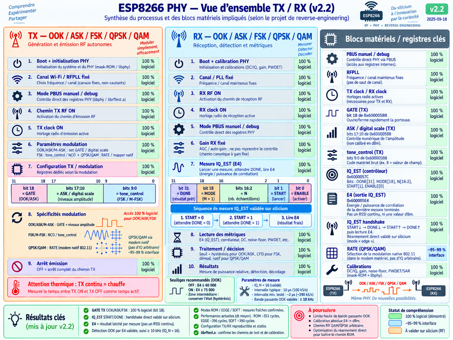
ESP8266 WLAN PHY — Reverse Engineering & RF Test Bench
README updated for consolidated reference v2.1 and the latest OOK/ASK/M-ASK reverse-engineering results.
Experimental research project for ESP8266 PHY/RF testing.
This repository explores low-level ESP8266 radio behavior for OOK / 2-ASK / M-ASK / FSK / M-FSK and documents research around QPSK / QAM.
It is not an official Espressif project, product, certification, or documentation.
 IMPORTANT SAFETY WARNING
Read this before flashing or transmitting.
This project directly manipulates low-level ESP8266 PHY/RF registers and ROM routines. It can keep the RF transmit chain active continuously, generate non-standard RF signals, and make the chip run very hot.
Project safety rules
- Use a Faraday cage, shielded RF enclosure, or a properly attenuated conducted setup for RF testing.
- Comply with the radio-frequency regulations and permitted operating conditions in your country.
- Do not leave the ESP8266 transmitting unattended.
- If the ESP8266 becomes very hot, unstable, smells unusual, resets repeatedly, draws abnormal current, or changes color: immediately disconnect power and let it cool completely.
- Do not assume that a larger numeric power value means a safe or linearly higher RF output.
APWRis a legacy/raw experimental control, not a calibrated dBm setting and not a pure analog-power knob.- Reverse-engineering of
rom_set_ana_inf_tx_scale()shows that its argument is split between an analog code and a returned digital-scale value; existing historical test firmware may ignore that returned digital value. - For routine tests, prefer conservative short-duration settings and do not use
APWR=255as a default. - Treat any long continuous-TX test as a thermal stress test: stop immediately if the module becomes unusually hot.
- Do not use this project to intentionally interfere with, block, degrade, or deny radio communications.
Critical note about TEST-TONEv5.yaml
TEST-TONEv5.yaml intentionally preserves historical/raw experimental defaults, including APWR=255.
Reverse-engineering has now clarified that rom_set_ana_inf_tx_scale(x) is not a simple linear analog-power setter. Functionally, the routine separates the argument into an analog control value and a digital-scale return value. Historical firmware often applies the analog side effect but does not automatically apply the returned digital value to the tone slot.
Therefore:
APWRmust not be read as a dBm value, percentage, or monotonic power scale;APWR=255is a historical/raw experiment value, not a recommended operating point;ASK 0..63is the preferred fast symbol-by-symbol amplitude control;- the analog path should normally be configured once per TX session, not toggled on every symbol.
For routine bench work, start conservatively, use short TX bursts, and verify the emitted level with RF instrumentation.
There is currently no software temperature protection in TEST-TONEv5.yaml.
Project goal
The goal is to understand and experimentally validate parts of the ESP8266 WLAN PHY that are normally hidden behind Espressif’s binary PHY implementation, and to use those findings to build reproducible low-level OOK/ASK/M-ASK research modems.
The project separates three kinds of results:
- Software/static reverse-engineering: behavior demonstrated from ROM, binaries, MMIO access, relocations, and control flow.
- Hardware/RF characterization: relationships such as code-to-frequency, code-to-power, settling time, phase continuity, spectral purity, and thermal behavior that must be measured on real silicon.
- Open questions: behavior that has not yet been demonstrated reliably.
The project does not assume that an internal register code has a simple physical interpretation unless it has been measured.
Repository contents
The repository contains both living reverse-engineering notes and frozen reference documents.
Main references
(ESP8266_PHY_MODULATIONS_REFERENCE_CONSOLIDEE_v2.1.md)
Consolidated French reference for OOK, ASK, FSK, M-FSK, QPSK and QAM.
(ESP8266_PHY_MODULATIONS_CONSOLIDATED_REFERENCE_v2.1_EN.md)
English consolidated reference.
(ESP8266_ASK_OOK_REFERENCE_OFFICIELLE_PROJET_v1.0.md)
Frozen TX OOK/ASK project reference.
(ESP8266_TX_FSK_MFSK_REFERENCE_OFFICIELLE_PROJET_v1.0.md)
Frozen TX FSK/M-FSK project reference.
(ESP8266_RX_OOK_ASK_REFERENCE_OFFICIELLE_PROJET_v1.0.md)
Frozen RX OOK/ASK project reference.
(ESP8266_RX_FSK_MFSK_REFERENCE_OFFICIELLE_PROJET_v1.0.md)
Frozen RX FSK/M-FSK project reference.
- ESP8266_WIFI_PHY_REVERSE_ENGINEERING*.md
Historical/living reverse-engineering documents.
Test firmware
The TEST-TONE*.yaml files are ESPHome-based experimental RF test firmwares.
The newest version currently present is:
TEST-TONEv5.yaml
It targets a Wemos D1 mini / ESP8266, runs the CPU at 160 MHz, disables the normal ESPHome logger UART, and exposes a simple 115200-baud serial console on UART0.
No normal Wi-Fi application connection is required for the test console.
The TEST-TONE*.yaml files should be treated as research artifacts, not production firmware and not pre-certified radio configurations.
Current TX model
OOK
The project identifies the normal tone gate as:
Tone slot 1: 0x600005B8
Gate: bit 18
Mask: 0x00040000
Fast OOK changes only the gate while keeping the RF path, analog configuration, digital scale, tone-control value, and TX clock stable.
Conceptually:
OOK 0 -> clear bit 18
OOK 1 -> set bit 18
The analog TX scale must not be switched on every OOK bit. Calling rom_set_ana_inf_tx_scale() per symbol adds internal I²C activity, settling, timing asymmetry, and unnecessary thermal/RF transients.
The OFF command is different: it shuts down the TX path rather than representing a fast OOK symbol.
ASK / digital scale
The software field used by the tone generator is:
bits 17:10
encoding = (-digital_scale) & 0xff
canonical digital_scale range = 0..63
The serial command is:
ASK 0..63
Important
ASK is the project’s name for this digital-scale control field.
It must not be interpreted as:
- a calibrated RF voltage,
- a percentage of output power,
- a dBm value,
- or a guaranteed monotonic amplitude control.
Its physical spectral effect must be measured.
Bench validation: digital 2-ASK works
On the tested ESP8266, a continuous tone was kept active while only the digital_scale field was alternated between two values. A tinySA showed two distinct RF amplitude levels while the same tone configuration remained active.
This is an important practical validation:
TX clock       = ON
RF path        = ON
tone gate      = ON
tone_control   = constant

digital_scale A
      ↓
RF amplitude A

digital_scale B
      ↓
RF amplitude B
This validates the practical 2-ASK amplitude-switching mechanism on the tested hardware. It does not establish a calibrated or linear digital_scale -> dBm law.
M-ASK modem architecture
The project now has all software-visible building blocks required to implement a fixed-gain M-ASK modem.
TX architecture
For M-ASK, keep the RF/tone state constant and change only digital_scale:
A0 -> digital_scale code 0
A1 -> digital_scale code 1
A2 -> digital_scale code 2
A3 -> digital_scale code 3
...
For 4-ASK, a Gray mapping is a useful starting point:
lowest RF level   A0 -> 00
                  A1 -> 01
                  A2 -> 11
highest RF level  A3 -> 10
The numeric digital_scale values must be selected experimentally. Do not assume that equally spaced control codes produce equally spaced RF powers.
RX architecture
The canonical RX path is:
RX RF ON
   ↓
RX clock ON
   ↓
PBUS debug / packet path isolated
   ↓
deterministic RX gain via PBUS
   ↓
IQ_EST
   ↓
E4 / correlation / DC metrics
   ↓
dynamic level calibration
   ↓
M-ASK slicer
The wrappers named phy_enable_agc() / phy_disable_agc() dispatch to CCA-related ROM functions and manipulate 0x60009B00[28]. This software path does not prove that the bit alone freezes analog gain. For M-ASK, use an explicitly programmed PBUS gain.
Dynamic per-packet calibration
Absolute received amplitude is not a reliable symbol reference because path loss changes with distance.
A packet should therefore begin with known amplitude symbols, for example:
A0 A1 A0 A1 A0 A1 ...              for 2-ASK
A0 A1 A2 A3 A0 A1 A2 A3 ...        for 4-ASK
The receiver estimates:
mu0, mu1                    for 2-ASK
mu0, mu1, mu2, mu3          for 4-ASK
For 2-ASK:
threshold = (mu0 + mu1) / 2
and the receiver decides relative to the current packet’s measured levels, not an absolute E4 or dBm value.
For 4-ASK:
T01 = (mu0 + mu1) / 2
T12 = (mu1 + mu2) / 2
T23 = (mu2 + mu3) / 2
This naturally tracks distance and path-loss changes as long as the levels remain separable.
A useful normalized separation metric is:
D(i,j) = |mu_i - mu_j| / sqrt(sigma_i^2 + sigma_j^2)
Dmin   = min(D01, D12, D23)
The best TX level set and RX gain are those that maximize Dmin without saturating the receiver.
New RX observables available
The reverse-engineered PHY exposes more than E4:
0x600005E4            energy / power metric
rom_get_corr_power()  normalized E, |Corr|^2, |DC|^2

0x60009824[11:0]      raw hardware noise-floor
0x60009B64[31:20]     processed noise-floor
E4 remains the simplest and fastest symbol metric. |Corr|^2, |DC|^2, and the noise-floor paths are especially useful for:
- preamble/calibration validation;
- saturation detection;
- rejecting poor calibration conditions;
- adaptive gain experiments;
- comparing candidate 4-ASK level sets.
Do not directly subtract the noise-floor register value from E4: they are not proven to share the same numeric scale.
RX gain is composite, not linear
The RX gain code is a 15-bit composite control distributed through PBUS. It must not be swept as if the numeric code were a linear dB value.
The PHY v6 builds a 127-entry gain table from 16 gain-step values derived from phy_init_data. The same code can be reduced to a baseband-gain index 0..29.
For systematic M-ASK experiments, sweep valid PHY gain-table entries or known PBUS configurations, not arbitrary numeric 15-bit increments.
3500-symbol/s migration path
The existing 3500-baud OOK modem can be adapted to 2-ASK with minimal structural changes:
existing:
bit 0 -> gate OFF
bit 1 -> gate ON

2-ASK:
bit 0 -> digital_scale A0
bit 1 -> digital_scale A1
The symbol scheduler, 8x IQ_EST oversampling, framing, 4b6b coding, and CRC can remain unchanged.
For 2-ASK, the main RX change is to learn A0/A1 from a known preamble before decoding payload data. For 4-ASK, extend this to four calibrated levels and three thresholds.
At 3500 symbols/s:
OOK / 2-ASK  -> 1 bit/symbol  -> 3500 raw bit/s
4-ASK        -> 2 bit/symbols -> 7000 raw bit/s theoretical before framing/FEC
The 4-ASK figure is a software/symbol-rate consequence, not a demonstrated RF throughput. Real performance depends on measured level separation and BER.
FSK / M-FSK
The software can hot-update the low tone-control field while keeping the following fixed:
RFPLL       fixed
channel     fixed
TX RF       active
TX clock    active
gate        active
digital scale fixed
Only tone_control changes between symbols in the proposed fast-FSK software path.
The firmware protects the field with:
K mask = 0x3ff
K range = 0..1023
For 2-FSK:
symbol 0 -> K0
symbol 1 -> K1
For M-FSK:
K0, K1, ... K(M-1)
Important
The project deliberately does not assume:
K -> frequency in Hz
to be linear, symmetric, or constant-step.
K is a raw hardware control code. The actual RF frequencies, wrap behavior, settling, jitter, phase behavior, occupied bandwidth, and unwanted emissions must be measured on the device. Project bench tests have not yet established a reliable usable FSK modem from this path, so FSK remains a software-path hypothesis requiring RF validation rather than a demonstrated modem.
QPSK / QAM status
The repository also documents the ESP8266 native QPSK / 16-QAM / 64-QAM paths.
What is established:
Wi-Fi-native BPSK/QPSK/16-QAM/64-QAM exists
modulation is selected by the native PHY/rate path
What has not been demonstrated:
arbitrary per-symbol QAM constellation injection
CPU-visible raw I/Q TX FIFO
general mapper bypass
arbitrary constellation index API
Therefore the tone-test firmware should not be described as an arbitrary QAM transmitter.
Serial console
Default serial configuration:
115200 baud
8 data bits
no parity
1 stop bit
Useful commands in TEST-TONEv5.yaml:
| Command | Purpose |
|---|---|
PHY |
Initialize/wake the PHY |
CH n |
Select Wi-Fi channel 1..14 when accepted by the SDK/domain |
FREQ MHz |
Select 2412..2472 MHz in 5 MHz steps, or attempt 2484 MHz |
ON |
Enable the experimental TX tone path |
OFF |
Stop sweep/test and shut down TX |
K n |
Set raw tone-control code, 0..1023 |
ASK n |
Set digital-scale field, 0..63 |
APWR n |
Set legacy/raw ROM analog/scale control; not linear power and not a pure analog-only knob |
OOK 0 / OOK 1 |
Toggle only the fast OOK gate while TX remains active |
KSWEEP min max |
Configure a K sweep |
KSTEP n |
Set K increment |
DWELL ms |
Set sweep dwell time |
SWEEP ON/OFF |
Start/stop the K sweep |
USTEP n |
Set Ultimate-mode K step |
UDWELL ms |
Set Ultimate-mode dwell |
UPASSES n |
Set Ultimate-mode pass count |
UAPWR n |
Set Ultimate-mode APWR |
ULTIMATE ON/OFF |
Start/stop the multi-channel stress/sweep test |
STATUS |
Show current state |
HELP |
Show firmware command list |
The presence of a command in the firmware does not imply that every setting is lawful for over-the-air operation in every jurisdiction.
Recommended first test
Use a shielded setup and begin conservatively.
Example:
PHY
APWR 32
ASK 63
K 8
ON
STATUS
Observe the signal with a spectrum analyzer.
Then stop TX:
OFF
If the device temperature rises quickly, disconnect power and do not continue until the cause has been understood.
Recommended 2-ASK amplitude check
A simple laboratory validation is to keep a tone active and alternate two ASK values while leaving the gate continuously enabled.
Example concept:
ASK level A for 500 ms
ASK level B for 500 ms
repeat
On a spectrum analyzer or tinySA zero-span display, the expected result is one tone whose amplitude alternates between two plateaus.
This verifies amplitude switching only. It does not calibrate either level in dBm.
Do not leave this test running unattended. A continuously enabled TX chain can heat the ESP8266 substantially more than normal packet Wi-Fi.
Recommended K characterization
A safer way to characterize the tone-control range is to keep one RF channel fixed and sweep K.
Example:
PHY
CH 6
APWR 32
ASK 63
ON
KSWEEP 0 1023
KSTEP 16
DWELL 5
SWEEP ON
Use a spectrum analyzer with suitable attenuation and, if useful, Max Hold.
Stop with:
SWEEP OFF
OFF
After identifying interesting regions, reduce KSTEP for finer characterization.
Ultimate mode
ULTIMATE ON is a stress / coverage experiment, not a normal modulation mode.
In TEST-TONEv5.yaml, it attempts to:
- walk through channels 1..14,
- sweep
Kacross 0..1023, - run a phase using
ASK=63, - run another phase using
ASK=0, - repeat for the configured number of passes.
This can create long periods of RF activity, substantial device heating, and uncharacterized spectral output.
Before using Ultimate mode
For routine characterization, explicitly set:
UAPWR 63
or lower before:
ULTIMATE ON
Prefer a short first measurement:
USTEP 16
UDWELL 1
UPASSES 1
UAPWR 63
ULTIMATE ON
Always keep the serial stop command ready:
ULTIMATE OFF
If the module becomes noticeably hotter than during ordinary Wi-Fi operation, stop the test and disconnect power.
Do not use Ultimate mode as a burn-in test.
Do not use Ultimate mode over the air to occupy spectrum, interfere with other systems, or test range against third-party networks.
OOK Reception Test
The TEST-RX-OOK-SPEED-v3.yaml file can be used to directly test OOK reception using the ESP8266 PHY IQ_EST block. The same measurement engine is also the canonical starting point for 2-ASK and M-ASK reception when used with deterministic PBUS gain and per-packet amplitude calibration.
The test flow is:
- enable the RX PHY;
- start an
IQ_ESTmeasurement; - wait for the
DONEbit; - read the RX metric from register
0x600005E4; - calibrate a known
OFFstate and a knownONstate; - automatically compute an OOK decision threshold.
Initialization
After flashing:
PHY
Example:
RX PHY: START
RX PHY: STATION_MODE=1
RX PHY: NONE_SLEEP=1
RX PHY: CH=6 CENTER=2437MHz SET_OK=1
RX PHY: READY (RX RF ON + RX CLOCK ON)
Check the RX Registers
REGS
Example:
REGS CTRL_DONE=80041003 DONE=1 CTRL_AFTER_DISABLE=00001000 E4=00004BD7(19415)
IQRES 580=00000000 584=00000000 588=00000000 58C=00000000 5DC=FFFDC400 5E0=FFFD85C0 5E4=00004BD7
The important field is:
DONE=1
This indicates that the IQ_EST measurement completed successfully.
A single measurement can also be triggered with:
SAMPLE
Example:
SAMPLE CH=6 E4=29233 CTRL_DONE=0x80041003 DONE=1 OOK=? TH=0 MIN=29233 MAX=29233 SPAN=0
OOK Calibration
With the transmitter in a known OFF state:
CAL OFF
Then, with a known ON carrier:
CAL ON
The firmware then automatically computes a threshold between the two measured levels.
It does not assume that E4 must increase when the carrier is present. The decision direction is determined automatically from the two calibration results.
Continuous Reception
RATE 50
STREAM ON
Example:
RX t=12345 CH=6 E4=26921 CTRL=80041003 DONE=1 OOK=1 TH=110787 MIN=17420 MAX=207399 SPAN=189979
RX t=12395 CH=6 E4=160769 CTRL=80041003 DONE=1 OOK=0 TH=110787 MIN=17420 MAX=207399 SPAN=189979
Stop streaming with:
STREAM OFF
The output:
OOK=0
or:
OOK=1
is the decision made from the E4 metric and the threshold obtained during calibration.
Test RX Measurement Speed
The YAML can also benchmark the maximum measurement rate of the IQ_EST engine.
Run:
BENCH 1000
Example measured with N=1024:
BENCH N=1024 COUNT=1000 TOTAL_US=28488 AVG_US=27 MIN_US=27 MAX_US=40 SPS=35102 1SAMPLE_BIT_CEIL=37037 DONE=1000/1000 E4MIN=7177 E4MAX=1274862
This corresponds to roughly:
35,000 RX measurements per second
An automatic sweep can be run with:
BENCHSWEEP
Measured results on the tested hardware:
| N | Measurements/s |
|---|---|
| 16 | 305810 |
| 32 | 292397 |
| 64 | 235294 |
| 128 | 169491 |
| 256 | 110375 |
| 512 | 64977 |
| 1024 | 35323 |
| 2048 | 18556 |
| 4096 | 9515 |
The integration window can be changed with:
IQN 16
or, for example:
IQN 256
After changing IQN, recalibration is recommended:
CAL OFF
CAL ON
because the E4 distribution may change with the integration window.
The same rule applies after changing RF channel or deterministic RX gain: any amplitude threshold learned under the old condition should be considered stale and recalibrated.
For M-ASK, do not reuse absolute E4 thresholds across arbitrary distance, channel, or gain changes. Learn the current packet’s amplitude levels from a known preamble.
Important: the number of measurements per second is not the same as the maximum reliable OOK bit rate.
To determine the real maximum OOK data rate, transmit a known bit pattern at increasing bit rates and measure detection errors.
Channel 14 / 2484 MHz note
TEST-TONEv5.yaml can attempt channel 14 / 2484 MHz.
Treat that function as laboratory-only unless you have independently established that your use is permitted.
For example, current Canadian RSS-247 requirements identify the relevant 2.4 GHz licence-exempt DTS/FHS band as:
2400 MHz to 2483.5 MHz
A center frequency of 2484 MHz is therefore outside that band edge.
Also remember that a center frequency being inside a permitted band is not sufficient by itself: sidebands, occupied bandwidth, out-of-band emissions, power, antenna gain, certification status, and other requirements can matter.
Thermal warning
The ESP8266 module and its RF output stage are not being operated here through a normal application-level Wi-Fi transmit workflow.
This firmware may:
- force the RF TX chain on,
- keep the TX clock active,
- bypass normal packet duty cycles,
- run continuous tones,
- repeatedly retune/sweep,
- and modify undocumented/internal controls.
Those conditions can produce much higher thermal stress than ordinary intermittent Wi-Fi traffic.
A continuous ASK test can be especially demanding because the tone gate may remain enabled at 100% RF duty cycle while only the digital amplitude field changes. This is not equivalent to normal packet Wi-Fi and can make the chip become very hot.
For modulation development, prefer:
short supervised TX bursts
    ↓
TX OFF / RX interval
    ↓
next burst
rather than leaving a continuous tone active for long periods.
No software temperature protection is currently provided by TEST-TONEv5.yaml.
Treat abnormal heating as a stop condition.
RF measurement precautions
When connecting the ESP8266 directly to RF test equipment:
- use appropriate attenuation,
- verify the analyzer/input power rating,
- avoid DC or RF conditions outside the instrument’s specified limits,
- prefer a shielded/conducted test arrangement,
- start at conservative settings,
- and verify the complete emitted spectrum rather than only the strongest peak.
When testing over an antenna, use a Faraday cage or equivalent shielded environment.
A Faraday cage is a risk-control measure, not a blanket legal exemption. Leakage and the actual emitted spectrum still matter.
Regulatory and legal warning
This section provides general information only and is not legal advice.
This repository can generate continuous or non-standard signals in the 2.4 GHz region.
The fact that the hardware can generate a signal does not mean that transmitting that signal over the air is permitted.
Licence-exempt does not mean unrestricted
Radio rules vary by country.
In Canada, RSS-247 currently covers relevant licence-exempt digital transmission/frequency-hopping systems in the 2400–2483.5 MHz band.
Licence-exempt operation is still subject to the applicable technical, certification, emission, power, and equipment requirements.
In other words:
“2.4 GHz licence-exempt” does not mean “any waveform, bandwidth, output power, firmware configuration, or frequency is permitted.”
Modified radio firmware and certification
Low-level RF firmware changes can affect whether an originally certified radio remains covered by its original certification.
Current Canadian RSS-Gen guidance recognizes firmware changes that affect RF characteristics as potentially relevant to certification and model status.
Therefore:
Do not assume that the original certification of an ESP8266 module or development board automatically covers the experimental PHY/RF modes in this repository.
Interference / jammer warning
This project is intended for controlled RF research and characterization, not for interference.
Do not use this project to intentionally block, disrupt, degrade, or deny radio communications.
In Canada, the Radiocommunication Act contains specific prohibitions concerning jammers and harmful/interfering radio operation.
Other jurisdictions
FCC, EU/RED, UK, Japanese, Australian, and other national rules differ.
Before any over-the-air use, check the current requirements of the regulator that applies to you.
Official Canadian references
-
ISED RSS-247:
-
ISED RSS-Gen:
-
Radiocommunication Act:
Regulations and standards change. Re-check the current versions before relying on this summary.
Reverse-engineering / third-party material notice
This repository primarily contains original experimental firmware, factual observations, and reverse-engineering notes about ESP8266 behavior.
Do not add or redistribute proprietary SDK archives, binary libraries, firmware images, source code, documentation, or other third-party material unless you have the right to do so.
Reverse-engineering, interoperability, security-research, copyright, anti-circumvention, and redistribution rules vary by jurisdiction and can depend on the specific facts.
This README does not claim that every possible reverse-engineering activity or redistribution is automatically lawful.
Repository licence status
At the time of this README update, the repository does not include a root LICENSE file.
Without an explicit licence, ordinary copyright rules apply by default. Publishing source code in a public GitHub repository does not automatically grant a general open-source licence for reuse, modification, or redistribution beyond the permissions provided by GitHub’s terms.
If the repository owner later wants to make the project explicitly open source, a separate licence can be added.
This README does not itself grant a software licence.
Research status summary
| Area | Project status |
|---|---|
| TX OOK software control | Closed at the documented software/MMIO level; gate-only modulation is canonical |
| TX 2-ASK digital-scale control | Closed in software and bench-observed as two distinct RF amplitudes on the tested unit |
| TX M-ASK digital-scale control | Software mechanism closed; code-to-dBm spacing and usable level count require measurement |
| RX OOK/2-ASK/M-ASK software path | Fixed-gain IQ_EST path closed; dynamic per-packet level calibration recommended |
| RX gain / PBUS path | Composite 15-bit mapping and BB gain structure documented; code-to-dB remains physical |
| RX noise-floor / Corr / DC metrics | Software-visible paths documented; useful for calibration/quality diagnostics |
| TX FSK/M-FSK command path | Software field-update path understood; reliable RF modem not yet demonstrated in project bench tests |
K -> Hz |
Hardware/RF characterization required |
| RX FSK CFO software path | Documented; fresh CFO on arbitrary non-802.11 tones requires silicon/baseband validation |
| Native Wi-Fi QPSK/QAM | Demonstrated through the native PHY/rate path |
| Arbitrary QAM constellation injection | Not demonstrated |
Terminology
When the documents say “official project reference”, this means:
the frozen reference document used by this reverse-engineering project.
It does not mean official Espressif documentation.
“ESP8266” and “Espressif” are used only to identify the platform being studied.
No affiliation, sponsorship, certification, or endorsement by Espressif is implied.
Disclaimer
This repository contains experimental reverse-engineering notes, firmware, and RF test material.
THE MATERIAL IS PROVIDED “AS IS”, WITHOUT WARRANTY OF ANY KIND.
To the maximum extent permitted by applicable law, no guarantee is made regarding:
- hardware safety,
- thermal safety,
- RF output level,
- spectral compliance,
- regulatory compliance,
- frequency accuracy,
- modulation accuracy,
- device-to-device repeatability,
- compatibility with every ESP8266 revision, SDK, board, or toolchain,
- protection of connected RF test equipment,
- or suitability for any particular purpose.
Users are responsible for:
- their own test setup,
- protecting hardware and test equipment,
- preventing harmful interference,
- complying with applicable radio and equipment regulations,
- determining whether a modified radio configuration remains covered by any certification,
- and respecting third-party copyrights, licences, and trademarks.
A disclaimer does not make prohibited radio operation legal and does not override mandatory law.
Start conservatively, measure, and stop immediately if the hardware behaves abnormally.