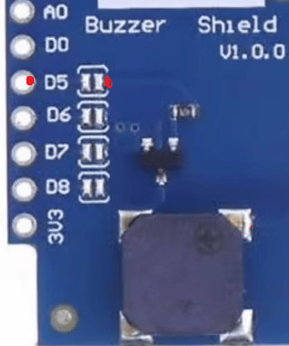
Try leaving those 2 lines out. The service is up but must be problem with output
nope, not worked
What about a bad connection on the board. Is the wemos soldered in?
yes soldered, and I went over them again. Unless I have melted the connection.
Put an ohme reader from one end of the pins to the other and they all bleeped.
D1 is soldered with pins, buzzer is soldered with female holes and then both pushed together
Continuity between pin and other side of that blob. Is that just solder or a resistor? Could be hardware or something simple in software that we can’t think of. Perhaps best to sleep on it.
So last report for tonight.
Continuity from D5 to left hand soldered | | but not right hand. This is the same with D6, D7 and D8.
Following the electrical circuit from | | in D5 has continuity in the soldered point in the middle of the board above the ?black resistor?
No, it is D5 which is gpio14
Sorry. It is D5 not D1. I’m half asleep. So it should go back to pin: 14 and not pin: 5. But it still wasn’t working when OP had it set at 14. So there may be something else wrong too.
Fresher eyes from the other side of the planet.
SJ3, SJ4, SJ5, and SJ6 are Solder Jumpers. You select one and use that GPIO. Since it’s a Wemos D1 Mini, I would use the D numbers, because that’s what’s on the silkscreen. Some purists insist on using Pin# or GPIO#, but it doesn’t matter as long as you are consistent,
So, D5 = gpio14 = pin14. Choose any numbering method that is easier for you.
Why are there four potential jumpers?
Simple. You could stack other shields on the Wemos D1 Mini for other purposes. The board designer lets you choose the GPIO pin to use so that there isn’t a conflict with other shields. Some shields don’t offer this flexibility. If this is your only shield, there are no conflicts which GPIO port to use. But you do need to put a solder blob on the appropriate SJ.
well explained @stevemann
This is mega useful. So are you telling me to solder blob the two solder joints that sit alongside the GPIO to connect the solder on the card?
Got is working. Perfect
Please post your final yaml file for others with a similar question in the future.
Really nothing to do with YAML more to do with soldering the two solder dots after D5.
but here goes:
output:
  - platform: esp8266_pwm
    pin: 14
    id: rtttl_out
 #   inverted: True
 #   zero_means_zero: True
    frequency: 1000.0

rtttl:
  output: rtttl_out
  on_finished_playback:
    - logger.log: 'Song ended!'

api:
    services:
    - service: play_rtttl
      variables:
        song_str: string
      then:
        - rtttl.play:
            rtttl: !lambda 'return song_str;'
        - output.turn_off: rtttl_out

#add the "song/tune you want into your automation when choosing service and looking for your named ESPdevice"


