BTW I have ordered these load cells and the HX711 board to try this. It’s been on my mind for a long time.
I think the clue is in the fact that you need to power the HX711 board(VCC) with 5 V. See this diagram https://cdn.sparkfun.com/assets/f/5/5/b/c/SparkFun_HX711_Load_Cell.pdf
The VDD pin of hx711 chip needs to be driven with 3.3 V from the Wemos D1.
Also refer to this on the Arduino forum
https://forum.arduino.cc/?topic=602275#msg4089890
Hmmm I’ll power it from my lab bench power supply and see if that yields other results.
Too bad, that would mean another power supply just for powering the HX711 since nor NodeMCU nor Wemos can supply 5V
Though other seem to have succeeded with just Wemos / NodeMCU…
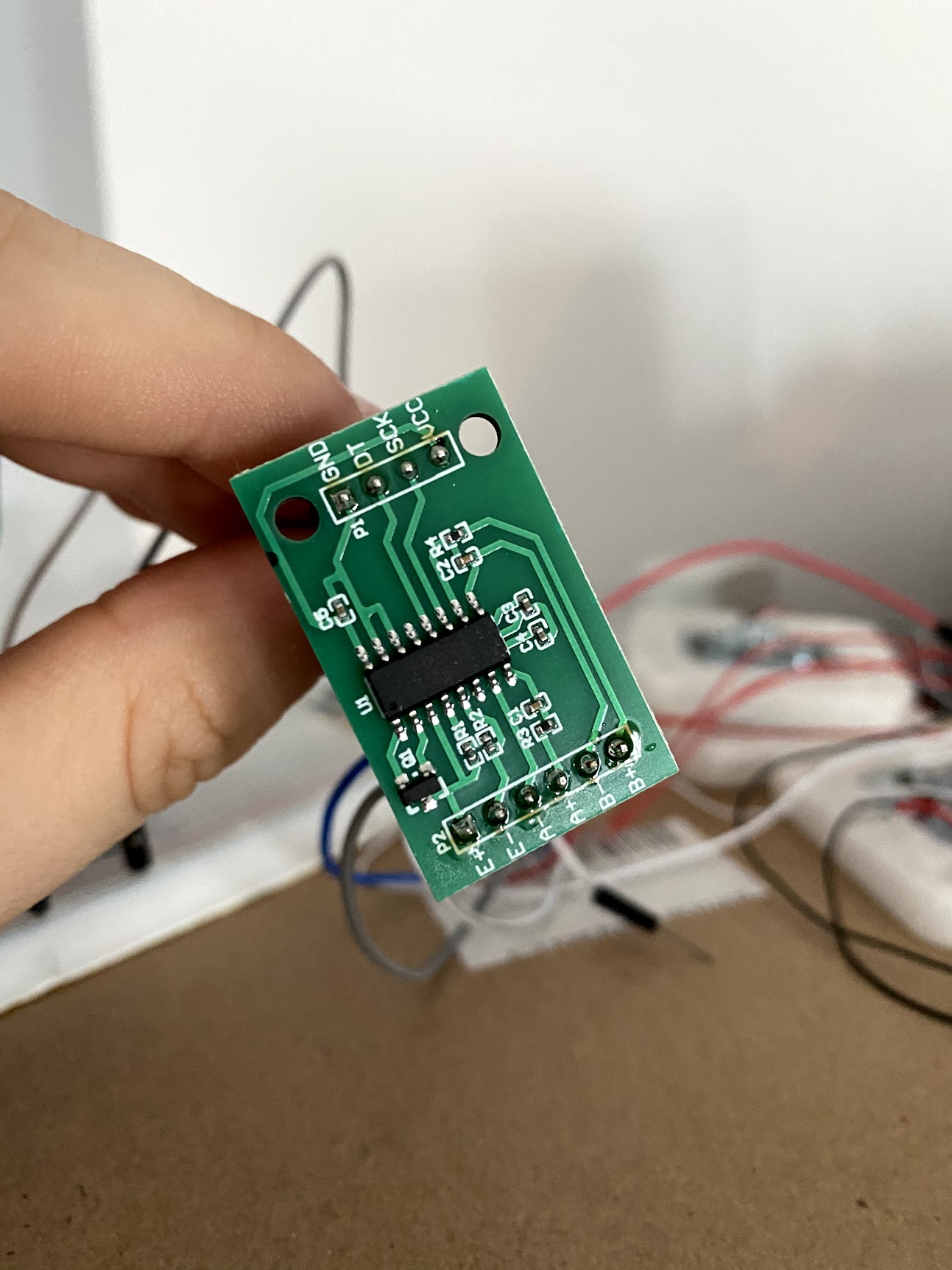
They have used the sparkfun HX711 that s VCC which is 5 V and VDD that is energised with 3.3 V. If your board has only VCC then you will need to lift Pin DVDD from the track and charge it with 3.3 V. Check the pin out from the datasheet marked in this post. I will be getting my HX711 board tomorrow in which I will do this mod.
Just a question where do you find the bases around the weight sensor
Thanks
My (green colored) HX711 and four load cells same as yours will arrive on Monday.
In the meantime I have prepped a ESP826612E. Firmware has been flashed now it will accept OTA.


@thibmaek is your HX711 a green one too. the first thing i will do is connect -E to ground. and later will modify the voltage divider comprising of the resistors R12 and R13. the load cells have to be worked o 5V and VDD to be charged with 3.3V for working with esp8266.
with a multimeter check if E- is connected to GND, if not just use a wirelink to connect them. and see if there is a change in the readings.
With the continuity function on my multimeter, checking E- and GND I get 695 as a reading.
In this mode the multimeter buzzer also sounds if there is continuity. Check for resistance it must be zero if these are connected or 1 if open.
My multimeter doesn’t have a beeper, but I’ll try with the resistance check
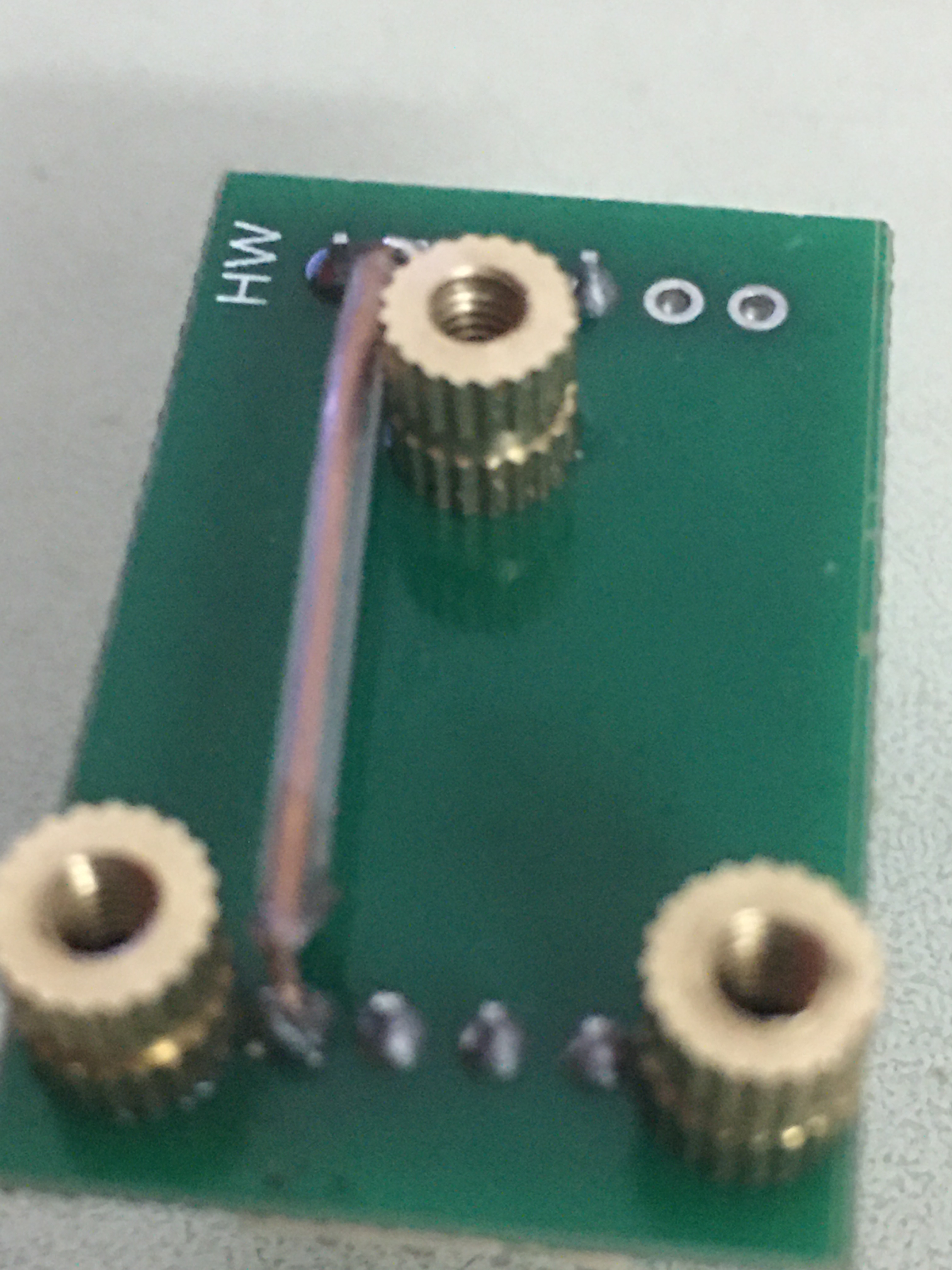
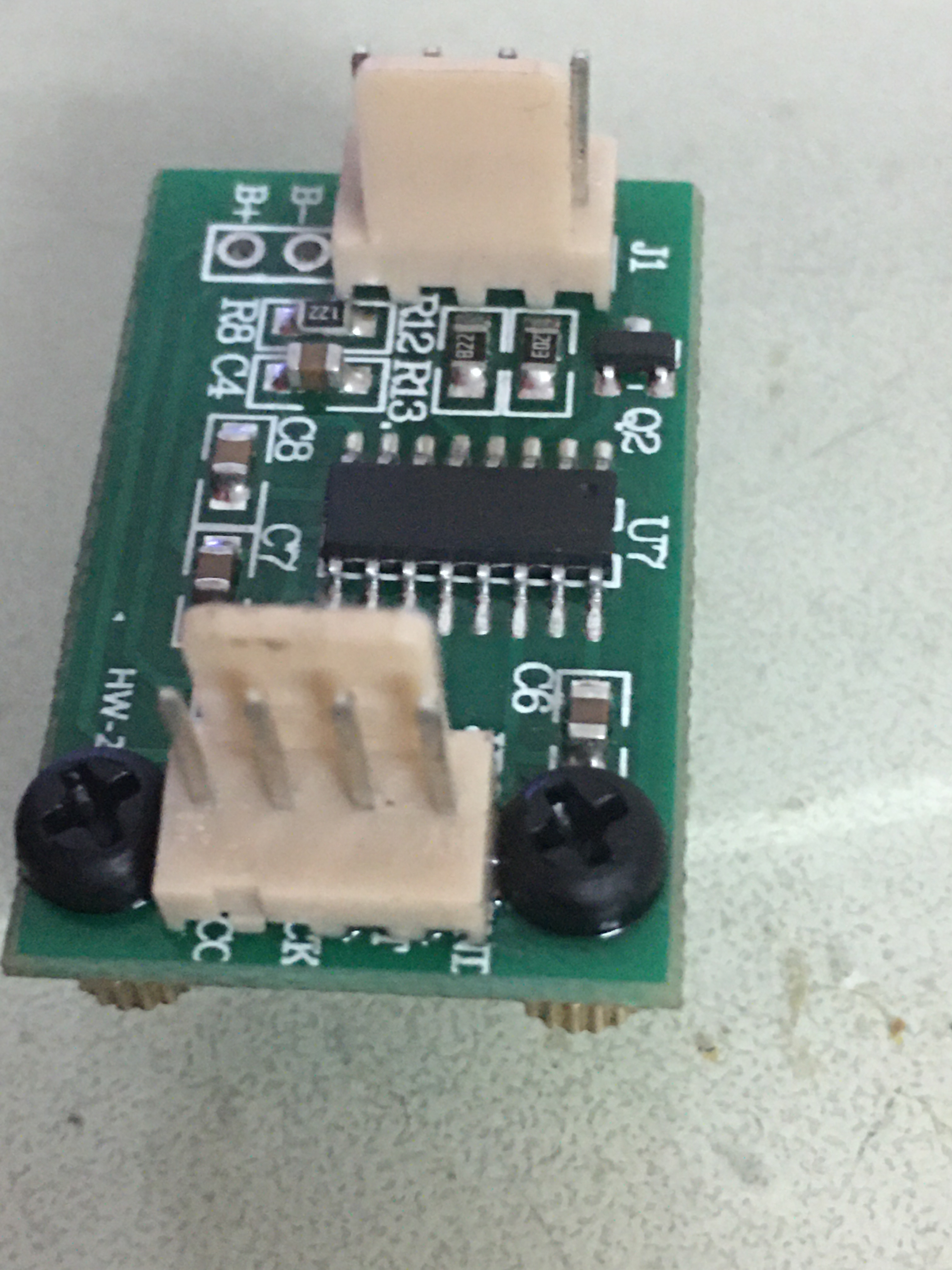
Fixed pcb mountings, soldered connector bases on both ends and soldered a link between E- and GND on the other side. This is how it looks.
@thibmaek, what changed in between you getting values of -8388608 and -2112820 at zero load?
-8388608 sounds like you’re saturating the input of the 24-bit ADC on the HX711 so I’m wondering if you’ve fixed that. My initial guess as to what could cause that is that the wheatstone bridge is not wired properly or the strain gage(s) is damaged. A quick way to check would be to disconnect the red wires from HX711, and measure the resistance between the wires that were connected to the E+ and E-, and then between A+ and A-. You should see 2000 ohm in both cases if it’s working properly.
Also, the way the sensor works, it will not function correctly if placed directly on the ground. The active portion of the load cell (highlighted red) needs to deflect with respect to the static portion (highlighted green) in order for the load cell to work properly. The printed base will probably work well, as it is likely designed to support the static portion and allow the center section to deflect down freely when the load cell is loaded. If the rivets are making contact with the ground, then it will not work properly.

FYI, I have an identical setup (Wemos D1 mini, same load cells & HX711) that is working fine without any other modifications.
1 Like
I’ll check this and will probably resolder the wires now and report back
Thank you for the explanation of how to test the resistance. Does it matter what pins you use on the D1_Mini? I’m using RX for clk and D4 for dout. Would you post you esphome code, thanks
You can consider changing the gain to 64 from 128.
@cyn I have it currently configured with the sample code on ESPHome.io HX711 configuration page for testing, as seen below. I am unable to answer your question regarding the D1 mini with certainty, as while I am an expert in load cells, I am merely a novice on the topic of ESP8266/ESPHome. I did read that by default, the logger occupies UART0 (TX/RX) and you may have to disable the logger in order to use them as GPIO.
# Example configuration entry
sensor:
  - platform: hx711
    name: "HX711 Value"
    dout_pin: D0
    clk_pin: D1
    gain: 128
    update_interval: 60s
1 Like
I just completed the combinator board, etched it and used green slider mask.
Any luck @thibmaek.

Will test the setup in a day or two.
