@Dilbert66 I wanted to let you know the WiFi issue was board related. I purchased 3 boards and the first two I tried had the WiFi reconnect issue. The third one works great and fast connects and reconnects if power is lost. I also posted the WiFi issue on Discussions · Dilbert66/esphome-dsckeybus · GitHub and couldn’t find a way to delete it since it is not relevant. Perhaps you can delete it.
@sidlauskas, logs would be helpful.
@olddawgpowers , interesting having two boards with the same issue. Glad you got it going. I’ll clear out the issue in the discussions, no worries .
If anyone interested, I’ve created a very simple design in KiCad for a USB-powered Wemos D1 Mini (ESP8266, but there are pin-compatible ESP32 versions) that can be wired easily on a 5*7 cm sized prototype PCB with mostly straight connections.

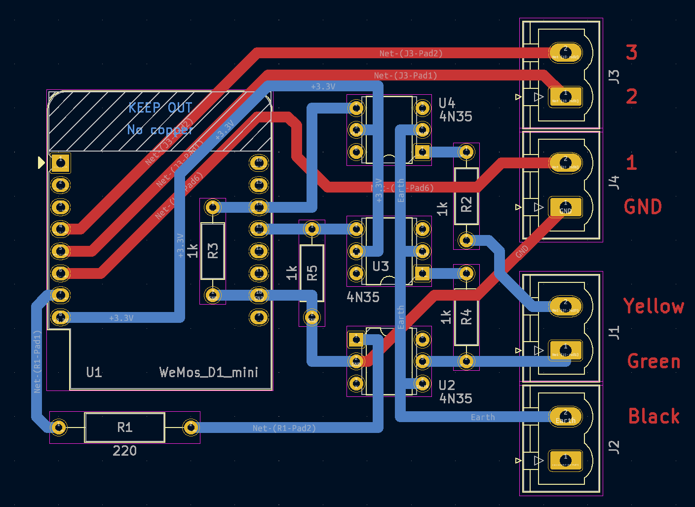
The extra connections with red wires are D5, D6, D7 of the ESP8266 used for non-critical door open sensors (like postbox door) that does not have to be wired into the alarm, and it was convenient to use the free pins of the Wemos D1.
Otherwise the same as the opto-coupler schematic on Dilbert66’s github page.


Hello @Dilbert66 I need some serious help… I have been trying to get my alarm panel into HA and this by far was the best project I’ve seen… very detailed. I have ran into an issue as I do not have a dsc alarm panel instead I have a ReadyGuardR-2 panel and all my sensors are honey well wireless sensors. I really was about to follow this guide and connect it to HA but I hit the wall… I tried using the multimeter to see the voltage of the cable but I got nothing back. I looked up the installation guide and see that those cables are for phone lines… I saw a data connector 7845GSM/7845i-GSM module pin on the panel not sure if I can use it here… leaving the pin diagram for your reference (attached)
also here is a full guide - https://www.alarmhow.net/manuals/First%20Alert/ReadyGuard%20R-2/ReadyGuard%20R2%20Installation%20Manual.pdf
Since I do not have the ports like you do in your dsc alarm panel… I was wondering if I can use the data pins (Syn IN, Data Out) to connect my esp8266? any help is much appreciated… really sorry if I wasn’t able to add proper information… please reply with any questions and I’ll do my best to answer.
Thanks in advance!!

@ akashsingh0454, sorry my software will not work with that system unfortunately so I cannot help with this.
Thank you for replying, appreciate it! I’ll keep looking I guess…
I’m trying to use the Custom Alarm Panel Card
When I click any numbers on the keypad I get this error: The esphome/dscalarm_alarm_keypress_partition service could not be called. service not found.
I am using the latest files from GitHub - Dilbert66/esphome-dsckeybus at new
I have set up a DSC pc1832 with an ESP32 microcontroller.
Everything looks like it’s working, i.e. The ESP32 looks like it is communicating with the DSC.
Any help to get the panel working would be appreciated.
See the log below:
INFO Reading configuration /config/esphome/dsp-alarm-esp32.yaml...
WARNING GPIO2 is a Strapping PIN and should be avoided.
Attaching external pullup/down resistors to strapping pins can cause unexpected failures.
See https://esphome.io/guides/faq.html#why-am-i-getting-a-warning-about-strapping-pins
INFO Detected timezone 'Europe/London'
INFO Generating C++ source...
INFO Compiling app...
Processing dsp-alarm-esp32 (board: nodemcu-32s; framework: arduino; platform: platformio/espressif32 @ 3.5.0)
--------------------------------------------------------------------------------
HARDWARE: ESP32 240MHz, 320KB RAM, 4MB Flash
LDF: Library Dependency Finder -> https://bit.ly/configure-pio-ldf
Dependency Graph
|-- WiFi @ 1.0
|-- ESPmDNS @ 1.0
|-- Update @ 1.0
Compiling /data/dsp-alarm-esp32/.pioenvs/dsp-alarm-esp32/src/main.cpp.o
Linking /data/dsp-alarm-esp32/.pioenvs/dsp-alarm-esp32/firmware.elf
RAM:   [=         ]  13.3% (used 43560 bytes from 327680 bytes)
Flash: [=====     ]  52.2% (used 958354 bytes from 1835008 bytes)
Building /data/dsp-alarm-esp32/.pioenvs/dsp-alarm-esp32/firmware.bin
esp32_create_combined_bin(["/data/dsp-alarm-esp32/.pioenvs/dsp-alarm-esp32/firmware.bin"], ["/data/dsp-alarm-esp32/.pioenvs/dsp-alarm-esp32/firmware.elf"])
Wrote 0xfa000 bytes to file /data/dsp-alarm-esp32/.pioenvs/dsp-alarm-esp32/firmware-factory.bin, ready to flash to offset 0x0
========================= [SUCCESS] Took 54.90 seconds =========================
INFO Successfully compiled program.
INFO Resolving IP address of dsp-alarm-esp32.local
INFO  -> 192.XXX.X.XXX
INFO Uploading /data/dsp-alarm-esp32/.pioenvs/dsp-alarm-esp32/firmware.bin (958464 bytes)
Uploading: [============================================================] 100% Done...

INFO Waiting for result...
INFO OTA successful
INFO Successfully uploaded program.
INFO Starting log output from dsp-alarm-esp32.local using esphome API
INFO Successfully connected to dsp-alarm-esp32.local


[23:59:34][C][logger:275]: Logger:
[23:59:34][C][logger:276]:   Level: DEBUG
[23:59:34][C][logger:277]:   Log Baud Rate: 115200
[23:59:34][C][logger:278]:   Hardware UART: UART0
[23:59:34][C][template.binary_sensor:018]: Template Binary Sensor 'dsp-alarm-esp32 Front door(z1)'
[23:59:34][C][template.binary_sensor:018]:   Device Class: 'door'
[23:59:34][C][template.binary_sensor:018]: Template Binary Sensor 'dsp-alarm-esp32 Garage door(z2)'
[23:59:34][C][template.binary_sensor:018]:   Device Class: 'door'
[23:59:34][C][template.binary_sensor:018]: Template Binary Sensor 'dsp-alarm-esp32 Back door(z3)'
[23:59:34][C][template.binary_sensor:018]:   Device Class: 'door'
[23:59:34][C][template.binary_sensor:018]: Template Binary Sensor 'dsp-alarm-esp32 Living room window(z4)'
[23:59:34][C][template.binary_sensor:018]:   Device Class: 'window'
[23:59:34][C][template.binary_sensor:018]: Template Binary Sensor 'dsp-alarm-esp32 Dining room window(z5)'
[23:59:34][C][template.binary_sensor:018]:   Device Class: 'window'
[23:59:34][C][template.binary_sensor:018]: Template Binary Sensor 'dsp-alarm-esp32 Family room window LF(z6)'
[23:59:34][C][template.binary_sensor:018]:   Device Class: 'window'
[23:59:34][C][template.binary_sensor:018]: Template Binary Sensor 'dsp-alarm-esp32 Family room window RF(z7)'
[23:59:34][C][template.binary_sensor:018]:   Device Class: 'window'
[23:59:34][C][template.binary_sensor:018]: Template Binary Sensor 'dsp-alarm-esp32 Basement windows(z8)'
[23:59:34][C][template.binary_sensor:018]:   Device Class: 'window'
[23:59:34][C][template.binary_sensor:018]: Template Binary Sensor 'dsp-alarm-esp32 Upstairs motion(z9)'
[23:59:34][C][template.binary_sensor:018]:   Device Class: 'motion'
[23:59:34][C][template.binary_sensor:018]: Template Binary Sensor 'dsp-alarm-esp32 Basement motion(z10)'
[23:59:34][C][template.binary_sensor:018]:   Device Class: 'motion'
[23:59:34][C][template.binary_sensor:018]: Template Binary Sensor 'dsp-alarm-esp32 Main floor motion(z11)'
[23:59:34][C][template.binary_sensor:018]:   Device Class: 'motion'
[23:59:34][C][template.binary_sensor:018]: Template Binary Sensor 'dsp-alarm-esp32 Test sensor(z17)'
[23:59:34][C][template.binary_sensor:018]:   Device Class: 'motion'
[23:59:34][C][template.binary_sensor:018]: Template Binary Sensor 'dsp-alarm-esp32 Partition 1 Ready'
[23:59:34][C][template.binary_sensor:018]: Template Binary Sensor 'dsp-alarm-esp32 Partition 1 Armed'
[23:59:34][C][template.binary_sensor:018]: Template Binary Sensor 'dsp-alarm-esp32 Partition 2 Ready'
[23:59:34][C][template.binary_sensor:018]: Template Binary Sensor 'dsp-alarm-esp32 Partition 2 Armed'
[23:59:34][C][template.binary_sensor:018]: Template Binary Sensor 'dsp-alarm-esp32 Trouble Status'
[23:59:34][C][template.binary_sensor:018]:   Device Class: 'problem'
[23:59:34][C][template.binary_sensor:018]: Template Binary Sensor 'dsp-alarm-esp32 Battery Status'
[23:59:34][C][template.binary_sensor:018]:   Device Class: 'problem'
[23:59:34][C][template.binary_sensor:018]: Template Binary Sensor 'dsp-alarm-esp32 AC Status'
[23:59:34][C][template.binary_sensor:018]:   Device Class: 'plug'
[23:59:34][C][template.binary_sensor:018]: Template Binary Sensor 'dsp-alarm-esp32 Panic Status'
[23:59:34][C][template.binary_sensor:018]:   Device Class: 'safety'
[23:59:34][C][template.binary_sensor:018]: Template Binary Sensor 'dsp-alarm-esp32 Fire partition 1 Status'
[23:59:34][C][template.binary_sensor:018]:   Device Class: 'safety'
[23:59:34][C][template.binary_sensor:018]: Template Binary Sensor 'dsp-alarm-esp32 Fire partition 2 Status'
[23:59:34][C][template.binary_sensor:018]:   Device Class: 'safety'
[23:59:34][C][template.binary_sensor:018]: Template Binary Sensor 'dsp-alarm-esp32 PGM 1'
[23:59:34][C][template.binary_sensor:018]: Template Binary Sensor 'dsp-alarm-esp32 PGM 2'
[23:59:34][C][template.binary_sensor:018]: Template Binary Sensor 'dsp-alarm-esp32 PGM 3'
[23:59:34][C][template.binary_sensor:018]: Template Binary Sensor 'dsp-alarm-esp32 PGM 4'
As I indicated on your github issues post, the log you posted does not show any communications with the dsc panel. All it shows is bootup preamble for the ESP. You also need to configure the alarm panel card to your own system. The default settings will not work as is.
Thanks, I’ll configure the settings to match my system.
Hello @wkchick, first of all, many thanks for sharing your PCB design.
May I have two questions regarding it:
- Do I understand correctly, that if I only want the core functionality, without ext in&out, then I only need to solder the part within the red circles on the below pic?
- For connecting the DSC, why there are two rows of holes for the terminals? Is this because some larger terminal can have two legs? I suppose if I only solder pins there, then I can use either of the rows marked as blue?

@olympia , your guess is right. You only need to solder the part within the red circles. I wired garage door sensor and outdoor siren to the DSC panel. That’s what the extra inputs and outputs designed for.
I used (3 or 4-pin) 0.1" pitch screwless terminal block (side entry) that came with 2nd row of pins.

If you use 0.1" pitch screw post or solder pins, you can choose either the outer or inner row. They are just the same.
Please also noted you can either use 1/4W metal film or surface mounted resistors but not both at the same time, solely depends on availability in your case.
Edited:
I hope the following photos can better illustrate the whole configuration.


1 Like
Hi @wkchick , thank you very much for the detailed response. These screwless terminals are looking great, I think I will also use these then.
Indeed it is really great how you designed that both 1/4W metal film or surface mounted resistors can be used. I have both and I will try surface mounted, but success will have a dependency on my soldering skills… If I fail, I will fall back to 1/4W metal film. 
To avoid any misunderstanding on my side (not sure my previous drawing was clear): the resistor islands marked with red below (R6, R7, R9, R10) are belonging to the extra in and outputs and I don’t need them just for the normal functionality, do I?

I had to purchase 5 of these boards so I have 4 extra (boards only) I will never use. I don’t claim to be a board designer, but the design works great and I have been using it for about 1 month with my DSC PowerSeries Alarm. If anyone would like one I am happy to send it to you for free (if you live in US). I can also provide a list of parts. The design uses a 30 Pin ESP32 ESP-WROOM-32 DEVKIT V1 board. Message me if you want one.


I’ll take one please. Many thanks.
Email me at [email protected].
Nice board design @wkchick , I did publish your pull request to master. At some point I will merge the new branch (my current dev branch) to master. For those using the new branch (which adds better multi partition and full lcd keypad emulation), @wkchick’s design is in the master branch. NOTE: I do recommend using an ESP32 if using the new branch.
@olympia , Not only R6, R7, R9 and R10 but also R8 and R11 are designed for extra inputs. In my case, pull up resistors (+12V) are needed for my garage door reed switches. Anyone can play with the resister values if they have a different configuration. For clarity, please refer to the schematic on the GitHub repository.
Please note I also uploaded a sample yaml file to my repository. Kindly take a look as I used different GPIO pins than standard ESP32.
@Dilbert66 Thank you. I forgot to thank you as you start this project and share your design in very details with rest of us.
OK, thank you!
I’ve just got the first version ready for testing (will do tomorrow, almost 1:00 am here.
I soldered R8 and R11 as well as I incorrectly thought that those are for the flasher pins.
Looks like that (many thanks again):

That email didn’t work for me.
Hi @Dilbert66 ,
I see the same issue with my freshly installed interface as sidlauskas.
Here are the logs from ESPHome. Do you have any idea what is causing this?
Thank your in advance!
[15:50:51][I][Paneldata: :976]: 05: 05 00 80 03 00 C7 00 C7 00 C7 01 00 00 00 00 00
[15:50:51][D][info:1778]: status 03, last status 01,line2status 53,selection 01,partition=1,skip=0
[15:50:51][D][text_sensor:067]: 'dscalarm line1': Sending state 'Secure System'
[15:50:51][D][text_sensor:067]: 'dscalarm line2': Sending state 'Zone 17  <>'
[15:50:51][D][text_sensor:067]: 'dscalarm Partition 1 Msg ': Sending state '03: Zones open'
[15:50:51][D][text_sensor:067]: 'dscalarm Partition 1 Status ': Sending state 'unavailable'
[15:50:51][D][binary_sensor:036]: 'dscalarm Partition 1 Ready': Sending state OFF
[15:50:53][I][Paneldata: :976]: 27: 27 00 80 03 00 C7 00 71 00 00 00 00 00 00 00 00
[15:50:53][D][info:1778]: status 03, last status 03,line2status 53,selection 01,partition=1,skip=0
[15:50:53][D][text_sensor:067]: 'dscalarm line1': Sending state 'Secure System'
[15:50:53][D][text_sensor:067]: 'dscalarm line2': Sending state 'Zone 17  <>'
[15:50:53][D][binary_sensor:036]: 'dscalarm Nappali (z5)': Sending state OFF
[15:50:53][D][text_sensor:067]: 'dscalarm zone status ': Sending state 'OK'
[15:50:53][I][Paneldata: :976]: 05: 05 00 81 01 00 C7 00 C7 00 C7 01 00 00 00 00 00
[15:50:53][D][info:1778]: status 01, last status 03,line2status 53,selection 01,partition=1,skip=0
[15:50:53][D][text_sensor:067]: 'dscalarm line1': Sending state 'System is Ready'
[15:50:53][D][text_sensor:067]: 'dscalarm line2': Sending state 'Zone 17  <>'
[15:50:53][D][text_sensor:067]: 'dscalarm Partition 1 Msg ': Sending state '01: Ready'
[15:50:53][D][text_sensor:067]: 'dscalarm Partition 1 Status ': Sending state 'disarmed'
[15:50:53][D][binary_sensor:036]: 'dscalarm Partition 1 Ready': Sending state ON
[15:50:53][I][Paneldata: :976]: 11: 11 00 AA AA AA AA AA AA AA 02 00 00 00 00 00 00
[15:50:53][I][Moduledata::976]: 11: FF 01 3F FC FF FF FF FF FF 03 00 00 00 00 00 00
[15:50:54][I][Paneldata: :976]: 27: 27 00 81 01 00 C7 10 80 00 00 00 00 00 00 00 00
[15:50:54][D][info:1778]: status 01, last status 01,line2status 53,selection 01,partition=1,skip=0
[15:50:54][D][text_sensor:067]: 'dscalarm line1': Sending state 'System is Ready'
[15:50:54][D][text_sensor:067]: 'dscalarm line2': Sending state 'Zone 17  <>'
[15:50:54][D][binary_sensor:036]: 'dscalarm Nappali (z5)': Sending state ON
[15:50:54][D][text_sensor:067]: 'dscalarm zone status ': Sending state 'OP:5'
[15:50:54][I][Paneldata: :976]: 05: 05 00 80 03 00 C7 00 C7 00 C7 01 00 00 00 00 00
[15:50:54][D][info:1778]: status 03, last status 01,line2status 53,selection 01,partition=1,skip=0
[15:50:54][D][text_sensor:067]: 'dscalarm line1': Sending state 'Secure System'
[15:50:54][D][text_sensor:067]: 'dscalarm line2': Sending state 'Zone 17  <>'
[15:50:54][D][text_sensor:067]: 'dscalarm Partition 1 Msg ': Sending state '03: Zones open'
[15:50:54][D][text_sensor:067]: 'dscalarm Partition 1 Status ': Sending state 'unavailable'
[15:50:54][D][binary_sensor:036]: 'dscalarm Partition 1 Ready': Sending state OFF
[15:50:56][D][text_sensor:067]: 'dscalarm beeps': Sending state '0'
[15:50:56][I][Paneldata: :976]: 27: 27 00 80 03 00 C7 00 71 00 00 00 00 00 00 00 00
[15:50:56][D][info:1778]: status 03, last status 03,line2status 53,selection 01,partition=1,skip=0
[15:50:56][D][text_sensor:067]: 'dscalarm line1': Sending state 'Secure System'
[15:50:56][D][text_sensor:067]: 'dscalarm line2': Sending state 'Zone 17  <>'
[15:50:56][D][binary_sensor:036]: 'dscalarm Nappali (z5)': Sending state OFF
[15:50:56][D][text_sensor:067]: 'dscalarm zone status ': Sending state 'OK'
[15:50:56][I][Paneldata: :976]: 05: 05 00 81 01 00 C7 00 C7 00 C7 01 00 00 00 00 00
[15:50:56][D][info:1778]: status 01, last status 03,line2status 53,selection 01,partition=1,skip=0
[15:50:56][D][text_sensor:067]: 'dscalarm line1': Sending state 'System is Ready'
[15:50:56][D][text_sensor:067]: 'dscalarm line2': Sending state 'Zone 17  <>'
[15:50:56][D][text_sensor:067]: 'dscalarm Partition 1 Msg ': Sending state '01: Ready'
[15:50:56][D][text_sensor:067]: 'dscalarm Partition 1 Status ': Sending state 'disarmed'
[15:50:56][D][binary_sensor:036]: 'dscalarm Partition 1 Ready': Sending state ON