However, on boot or reset, the relay triggers momentarily which causes the connected device to come on which is unwanted behaviour. I have read quite a few articles describing the state of the pins on boot so I have tried to connect to one that is “High” on boot, but it seems to have had no effect.
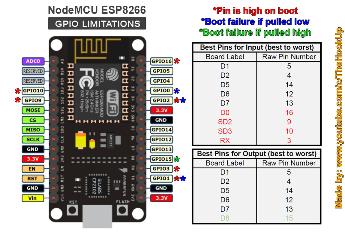
Thanks, that website is really useful. It mentions another article and that provides a great explanation of which pin is best to use as in- or output and why: http://www.thesmarthomehookup.com/post-320/
tl;dr
However that didn’t solve my problem
For clarification, I’m using a “Wemos” D1 Mini from Aliexpress. It has less pins than the NodeMCU, but the pins that are present and have the same label (D0-D8) are connected to the same GPIO pins as on the NodeMCU, which may be obvious to some but I wanted to cover all bases.
Turns out the solution was right in front of me from the beginning!
After creating/compiling the firmware for the first time, a directory with the device’s name specified in the YAML file is created (“relay_test” in my example) and in there, a “src” subdirectory with the file “main.cpp”. After reading the documentation to create a custom sensor I worked out how to edit “main.cpp” and manually inserted the digitalWrite() statement, but for this to work with esphomeyaml requires an extra flag in the device’s YAML file:
relay_test.yaml

esphomeyaml:
  name: relay_test
  platform: ESP8266
  board: d1_mini
  use_custom_code: True  #<<---- this is the extra flag

#wifi, mqtt, ota etc goes here

switch:
  - platform: gpio
    pin:
      number: D5 #remember to change in main.cpp if changed here
      inverted: True
    name: "Relay 1"
#two more relays on D6 and D7 but the YAML is the same
relay_test/src/main.cpp

void setup() {
  //write HIGH to the relay pins before anything else to avoid
  //triggering on boot / reset (this is for active low relays)
  digitalWrite(14, HIGH); //D5
  digitalWrite(12, HIGH); //D6
  digitalWrite(13, HIGH); //D7
  // ===== DO NOT EDIT ANYTHING BELOW THIS LINE =====
  // ========== AUTO GENERATED CODE BEGIN ===========
  ....
}
The pinMode is set by the auto generated code, so in my solution digitalWrite() is called before pinMode() as described in the explanation in the first post.
Changes made to main.cpp (outside the auto generation area) are persistent, so any changes to my relay_test.yaml won’t break the fix. Of course if you change GPIO pins in YAML you would have to manually edit the number in the digitalWrite() statement.
This has (so far) fixed the problem of triggering the relay on boot and reset!
Please note that restore_mode takes into account the value of inverted, so for restore_mode: ..._OFF when inverted is true, the switch will be off, which means the GPIO is HIGH.
hello. I use same hardware. Use this solution, but have little problem.
When ESP loaded, in web UI it show all switches enabled, but really they are disabled.
So i need click on this switches to move they in disabled state.
How can i fix it?
I am struggling with I think might be a similar issue. I am using an idea from link below to connect large quantities of relays using ESP 8266 + MCP23017
Despite using restore_mode: ALWAYS_OFF during reset/boot after power off there is a quick short trigger of all relays one ater each other. Have anyone of You had this issue or was able to solve this problem? Below my code + logs from ESPHome.
Hm… i’m just guessing, but why do you use “inverted: true” with MCP? That might be the cause of relay trigger: ESP board first defines MCP pins as output. Since you have relays connected reverse in this moment relay activates. Then board re-defines pins as reverse, so pin changes state and relay releases → startup click happens.
I just play with MCP and my relays doesn’t move at startup, but, as said, i don’t have inverted outputs. MCP has normal outuputs, not open collector or open drain (ok it does, but only if you specifically want them to be), so you just connect relay between output and ground (and add diode in reverse, of course).
I use “inverted: true” because in case it is as default (false) then all relays are ON after boot. I need to have them OFF during boot and use them as momentary switches, that is why a template is used to turn off after 500ms.
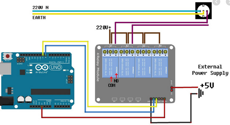
I have tried now again with inverted as false to be sure that it affects my idea but it is as mentioned above. My setup is exactly connected as below but with change that I use all other 8 pins from MCP for second 8 relays.
Sure, code attached. I have reversed only inputs.
I’m not sure, how your relay board works, but it seems that it’s reversed: when GND relay is active and when it’s +3,3V relay is deactivated, that’s why you get all relays active at startup when you use inverted: false. Check out what function have that jumper on the right of relay board - maybe you can reverse function with it.
I have relays connected directly to MCP outputs (not through optocouplers) and in such way that +3,3V from MCP activates relay.
EDIT: i just tested direct outputs (from ESP8266, GPIO12, 13 and 14) with inverted: false and restore_mode: always off (or default_off). Relay still clicks at startup… If i use inverted:true, and re-wire my relays accordingly, then startup click doesn’t happen, no matter if i have statement “restore_mode…” present or not, so above solution doesn’t work at all…
As I understand this jumper allows to connect to relay module external power supply to trigger relay which is isolated from the one from MCP (in our case).
So is there any other idea to avoid this triggering during boot? Maybe not software but hardware? The worst thing is that during blackout and having the power back it will shortly start all my lights in house and open the gates…
Maybe there is a ready module which will delay providing power supply on relays after power is restored?
I know how you feel, i use similar setup for garage door, too, and startup click is absoutely not acceptable.
I can’t tell how your realy board works, but it seems that relays are triggered when you have GND at inputs, is that correct? (You can test them by connect, say, IN1 to GND and to Vcc and see when relay is turned on.)
If so, one option is to use a different relay board, which has selectable low/high active trigerring (you need relay active when +5V is at input) like THIS ONE
The main point is NOT to use “reversed:true” with MCP. At bootup all MCP pins are by default inputs, then ESP8266 defines them as outputs (set them at low state, thus activating your relays), next it changes state to high, because you have inverted output defined and relays deactivate. And this causes relay click.
Or, if you are good in soldering and electronics you could make an adapter with transistors, like picture below. I used this setup for my test, explained above (in bold).
esp8266_restore_from_flash
With this option you can control where the state of certain components is kept on the ESP. Components like light, switch, fan and globals can restore their state upon boot.
However, by default this data is stored in the “RTC memory” section of the ESP8266s. This memory is cleared when the ESP8266 is disconnected from power. So by default the state cannot be recovered after power loss.
To still have these components restore their state upon power loss the state can additionally be saved in flash memory by setting this option to true.
Beware: The flash has a limited number of write cycles (usually around 100 000), after that the flash section will fail. So do not use this option when you have components that update rapidly. These include GPIO switches that are used internally (disable restoring with the restore_mode option), certain light effects like random and the on_value_range trigger.
I’ve found a relay with delay on power on which I am planning to use for delaying power on relays board. It is not the best solution but in case of blackout it will not trigger relays during boot. What is Your opinion?
@lordzid - I already tought about this but it has to many cons with limitation of writing cycles for my solution.
on_boot (Optional, Automation): An automation to perform when the node starts. See on_boot. can this help you? the operation will be performed before loading the main when.
I have not seen earlier ‘on_boot’ options but this might lead to solving another way around my challenge using software solution. Will make some tests and get back with feedback.
wow… you really have quite big block of relays…
Your idea with power delay is a good one. Connect additional relay to an empty GPIO pin of ESP board. Then configure “on boot” function in ESPHome: you define delay and then turn on a relay. That way relay will turn on after, say, 2 seconds.
It’s something like this:
You can make this output internal, so it won’t show in HA interface.
Regarding connection type: you’ll have to experiment. First try to connect a relay normally, with one transistor. If bootup-click appears then connect it reversed (via above two-transistor circuit). (you don’t use MCP module here!)
EDIT: or maybe you could use one of MCP relays. Define one of them as reversed and so i guess it should turn on at boot and off after two seconds…
Just in case anyone else finds themselves in a similar situation…the proposed solutions earlier in the thread did not work for me, and it turns out that the reason is I am using a Wemos D1 Mini clone, and the pins I chose (D4, D3) apparently cause the relay to switch when the board boots.
I tried adding a digitalWrite to make the pins high during setup, no dice. I tried adding the RESTORE_DEFAULT_OFF, didn’t work.
Then I found this article on using relays with esp8266 boards, which suggested that the safest pins to use are: GPIO 5, GPIO 4, GPIO 14, GPIO 12 and GPIO 13.
I changed my wiring to use D6 and D7 (GPIO 12 and 13), and the relay trigger on reset went away.
So if you’re having issues with relay triggering on reset, and the YAML or code fixes don’t work for you, try using a pin from the list above.