ESP8266/RS485 on Growatt inverter - spurious data between updates

Hi Folks,

I connected an RS485 module to an ESP8266 D1 mini to read data locally from from my Growatt inverter (SPH5000). It works but a few of the addresses return random huge anomalous data between updates which I’ve set to every 10 seconds. Some of the channels are from the ESPhome component and the others are reading the RS485 channels (found in the inverter datasheet).

I’ve added a filter on to a couple of channels but this only clips the data to the max range I’ve set.

Is there any way to disregard or stop this data passing through to Home Assistant?
Gif of the random data:

History graph is unuable:

Imgur

Filtered channel graph is also full of noise:
Imgur

The RS485 module is connected to a spare port on the inverter not the standard port used for the Growatt wifi module, I still have that connected separately.

esphome:
  name: growatt

esp8266:
  board: d1_mini

# Enable logging
logger:

# Enable Home Assistant API
api:
  encryption:
    key: "xxx"

ota:
  password: "xxx"

wifi:
  ssid: !secret wifi_ssid
  password: !secret wifi_password

  # Enable fallback hotspot (captive portal) in case wifi connection fails
  ap:
    ssid: "Growatt Fallback Hotspot"
    password: "xxx"

captive_portal:
    
# Example configuration entry
uart:
  - id: uart1
    baud_rate: 9600
    tx_pin: GPIO12
    rx_pin: GPIO14

modbus:
  uart_id: uart1
  flow_control_pin: GPIO4

modbus_controller:
  - id: epever
    ## the Modbus device addr
    address: 0x1
    setup_priority: -10

sensor:
  - platform: growatt_solar
    update_interval: 10s
    protocol_version: RTU2


    phase_a:
      voltage:
          name: "Growatt Voltage Phase A"
      current:
          name: "Growatt Current Phase A"
      active_power:
          name: "Growatt Power Phase A"
          filters:
            lambda:
              float MIN_VALUE = 0.0;
              float MAX_VALUE = 7000.0;
              if (MIN_VALUE <= x && x <= MAX_VALUE) return x;
              else return {};

    pv1:
      voltage:
          name: "Growatt PV1 Voltage"
      current:
          name: "Growatt PV1 Current"
      active_power:
          name: "Growatt PV1 Active Power"

    pv2:
      voltage:
          name: "Growatt PV2 Voltage"
      current:
          name: "Growatt PV2 Current"
      active_power:
          name: "Growatt PV2 Active Power"

    active_power:
      name: "Growatt Grid Active Power"

    pv_active_power:
      name: "Growatt PV Active Power"
      filters:
        - lambda:
            float MIN_VALUE = 0.0;
            float MAX_VALUE = 6000.0;
            if (MIN_VALUE <= x && x <= MAX_VALUE) return x;
            else return {};

    frequency:
      name: "Growatt Frequency"

    energy_production_day:
      name: "Growatt Today's Generation"

    total_energy_production:
      name: "Growatt Total Energy Production"

    inverter_module_temp:
      name: "Growatt Inverter Module Temp"


  - platform: modbus_controller
    name: "Battery Charge"
    address: 1014
    register_type: "read"
    unit_of_measurement: "%"
    icon: mdi:flash
    value_type: U_WORD
    accuracy_decimals: 0


  - platform: modbus_controller
    name: "Battery Discharging Power"
    address: 1009
    register_type: "read"
    unit_of_measurement: kW
    device_class: power
    icon: mdi:flash
    value_type: U_DWORD
    accuracy_decimals: 3
    filters:
    - multiply: 0.0001

  - platform: modbus_controller
    name: "Battery Charging Power"
    address: 1011
    register_type: "read"
    unit_of_measurement: kW
    device_class: power
    icon: mdi:flash
    value_type: U_DWORD
    accuracy_decimals: 3
    filters:
    - multiply: 0.0001

  - platform: modbus_controller
    name: "Load"
    address: 1021
    register_type: "read"
    unit_of_measurement: kW
    device_class: power
    state_class: measurement
    icon: mdi:solar-power
    value_type: U_DWORD
    accuracy_decimals: 3
    filters:
    - multiply: 0.0001

I am also using ESP8266, but NodeMCU board, and have problems communicating with the inverter via RS-485.
My setup is the folowing:

uart:
  id: mod_bus
  tx_pin: GPIO13
  rx_pin: GPIO12
  baud_rate: 9600
  stop_bits: 1
  debug:
    direction: BOTH

modbus:
  id: modbus1
  uart_id: mod_bus
  flow_control_pin: GPIO4
  send_wait_time: 3s
  
modbus_controller:
  - id: growatt
    address: 0x01
    modbus_id: modbus1
    command_throttle: 2s
    update_interval: 30s

And here are the errors that I get:

08:05:53	[D]	[uart_debug:114] >>> 01:04:00:19:00:01:E0:0D
08:05:53	[W]	[modbus:105]	Modbus CRC Check failed! 1B01!=1A
08:05:53	[D]	[uart_debug:114] <<< 00:01:04:02:00:66:39:1A:00

As far as I can tell, the problem of Modbus CRC fail is because the received package begins with an extra 0x00 byte which should not be there. A modbus package begins with the address, which in this case is 0x01, the second byte of the package.

The same thing that our setups have in common is the usage of softserial, but at such low baudrate, it should not be a problem.

Anyways, I will try to use hardware serial and see if the problem is solved.

Or stop bits 2

I tried changing the stop bits to 2 but it didn’t like it.

I also tried various baud rates but it only works at 9600.

I enabled the debugging and get loads of “CRC check failed” messages. I’ll check my wiring and add shielding where I can but I’ll be away from home for a couple of weeks. If it’s a hardware issue it’s likely between my TTL -RS485 adapter and the ESP.

I managed to solve my issue.
I am using a cheap RS485 board:


I removed R7 which is the 120 ohm termination resistor and the CRC failed error did not appear anymore.
Removing the termination resistor should make things worse, not better, since I only have this board connected on the RS485 port of the inverter, but anyways, it works!

Thanks. That’s the same board I have. I’ll give it a try, I had planned on adding a resistor across A/B when I got a chance but I didn’t realise one was already on the board.

Did you come right. I have tried everything i cannot get my spf5000es to communticate. I have a nodemcuv3 with the same rs485 board. DI is wired to GPIO12, RO is wired to GPIO13 and the RE and DE are wired to GPIO4. I copied your setup but all i get is sending on the uart log without the resistor and with the resistor i just get CRC errors

I removed R7 on the RS485 board and I get less CRC errors but still get random high values coming through. I’ve still to try adding resistors on the terminals when I get time. I resoldered my boards with shorter wire connections to reduce noise also.

There’s info on your inverter here. I’d double check which pins you’re using and swap around.

Did you use 1 and 2 for RS485B and A or did you use pins 7 and 8

I can’t remember but I think it may have been different pins entirely (maybe 3&4), my inverter is an SPH model.

Try each pair until you get Comms. You will see the data come through on the esphome log. Also check the protocol version (RTU or RTU2). I found a data sheet for my inverter online which had the modbus addresses listed (I’m not sure all the addresses were accurate though).

Here’s a data sheet for the SPF models.

Hi @Gregsy, I know it’s been a while since this message was posted, but I have the same inverter as you and I would like to ask you for help on how to do it, can you answer these questions?

  1. Do you have the Modbus documentation of the SPH?
  2. How do you have it connected to the rs485 connector with rj45?
  3. Can you tell me what I have to buy?
    4.Can you pass me the configuration for esphome that you have?

Thank you very much, sorry for the inconvenience.

Hi Maikol.

I’ll get back to you in the next few days, I’m working away from home.

I should be able to pull all the info together and post it soon.

I used a D1 mini esp board and a TTL to RS485, I get quite a few CRC errors and it’s probably the cheap RS485 converter so you may want to search for something better.

Failsave resistors!

The above words did not appear anywhere in this thread, so I feel the need to mention it here:

If you research how an RS485 bus is supposed to operate on the physical layer then it should become clear that there are periods where all connected transceivers are idle and high-Z. Therefore there must be pull-resistors somewhere on the bus to pull the voltage levels safely towards the idle (“MARK”) level. These pull resistors are called failsafe resistors.

Looking at the schematics for the TTL to RS485 converter it has built in fail safe resistors and a termination resistor. I removed the termination resistor from my board and added a different value resistor to the terminal connectors but no luck.

Here are some resources I used to connect to my Growatt SPH5000 inverter:

Configuring Growatt SPH inverter - I used pins 4&5 as per the table in the troubleshooting section further down.

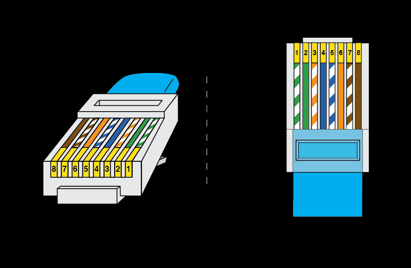
Use an old ethernet cable, cut one end off and connect pins 4&5 to the A&B- of the RS485 converter. (I’m in the UK, I believe different countries inverters may use different pins).
I used an ESP8266 D1 Mini board wired to a MAX485 TTL to RS485 converter board. Soldering required.

The D1 Mini has 5v and 3.3v pins for use and a micro USB connection. I powered this from the inverters unused USB port. Wire as per this:

https://github.com/jkairys/growatt-esp8266/blob/d7adc082a09bbadaa0b79988d987d56f0f251f5f/doc/Growatt%20PV%20Inverter%20Modbus%20RS485%20RTU%20Protocol%20V3.04.pdf - This file has modbus addresses for data you might want. I have what I need in my code below.

The upper code uses ESPHome growatt integration and the other addresses are modbus.

esphome:
  name: growatt

esp8266:
  board: d1_mini

# Enable logging
logger:
  baud_rate: 0
# Enable Home Assistant API
api:
  encryption:
    key: "xxxxxxxxxxxxxxxxxxxxxxxxxxxxxxxxxx"

ota:
  password: "xxxxxxxxxxxxxxxxxxxxxxxxxxx"

wifi:
  ssid: !secret wifi_ssid
  password: !secret wifi_password

  # Enable fallback hotspot (captive portal) in case wifi connection fails
  ap:
    ssid: "Growatt Fallback Hotspot"
    password: "xxxxxxxxxxxxxx"

captive_portal:
    
# Example configuration entry
uart:
  - id: uart_0
    baud_rate: 9600
    tx_pin: GPIO12
    rx_pin: GPIO14
    rx_buffer_size: 2048
    debug:
      direction: both

modbus:
  uart_id: uart_0
  flow_control_pin: GPIO4
  send_wait_time: 10ms
  disable_crc: true

modbus_controller:
  - id: epever
    ## the Modbus device addr
    address: 0x1
    setup_priority: -10
    command_throttle: 25ms


sensor:
  - platform: growatt_solar
    update_interval: 5s
    protocol_version: RTU2


    phase_a:
      voltage:
          name: "Growatt Voltage Phase A"
          filters:
            lambda:
              float MIN_VALUE = 210.0;
              float MAX_VALUE = 270.0;
              if (MIN_VALUE <= x && x <= MAX_VALUE) return x;
              else return {};
      current:
          name: "Growatt Current Phase A"
          filters:
            lambda:
              float MIN_VALUE = 0.0;
              float MAX_VALUE = 45.0;
              if (MIN_VALUE <= x && x <= MAX_VALUE) return x;
              else return {};
      active_power:
          name: "Growatt Power Phase A"
          filters:
            lambda:
              float MIN_VALUE = 0.0;
              float MAX_VALUE = 7000.0;
              if (MIN_VALUE <= x && x <= MAX_VALUE) return x;
              else return {};

    pv1:
      voltage:
          name: "Growatt PV1 Voltage"
          filters:
            lambda:
              float MIN_VALUE = 0.0;
              float MAX_VALUE = 400.0;
              if (MIN_VALUE <= x && x <= MAX_VALUE) return x;
              else return {};
      current:
          name: "Growatt PV1 Current"
          filters:
            lambda:
              float MIN_VALUE = 0.0;
              float MAX_VALUE = 20.0;
              if (MIN_VALUE <= x && x <= MAX_VALUE) return x;
              else return {};
      active_power:
          name: "Growatt PV1 Active Power"
          filters:
            lambda:
              float MIN_VALUE = 0.0;
              float MAX_VALUE = 3000.0;
              if (MIN_VALUE <= x && x <= MAX_VALUE) return x;
              else return {};

    pv2:
      voltage:
          name: "Growatt PV2 Voltage"
          filters:
            lambda:
              float MIN_VALUE = 0.0;
              float MAX_VALUE = 400.0;
              if (MIN_VALUE <= x && x <= MAX_VALUE) return x;
              else return {};
      current:
          name: "Growatt PV2 Current"
          filters:
            lambda:
              float MIN_VALUE = 0.0;
              float MAX_VALUE = 20.0;
              if (MIN_VALUE <= x && x <= MAX_VALUE) return x;
              else return {};
      active_power:
          name: "Growatt PV2 Active Power"
          filters:
            lambda:
              float MIN_VALUE = 0.0;
              float MAX_VALUE = 3000.0;
              if (MIN_VALUE <= x && x <= MAX_VALUE) return x;
              else return {};

    active_power:
          name: "Growatt Grid Active Power"
          filters:
            lambda:
              float MIN_VALUE = 0.0;
              float MAX_VALUE = 12000.0;
              if (MIN_VALUE <= x && x <= MAX_VALUE) return x;
              else return {};

    pv_active_power:
          name: "Growatt PV Active Power"
          filters:
          - lambda:
             float MIN_VALUE = 0.0;
             float MAX_VALUE = 6000.0;
             if (MIN_VALUE <= x && x <= MAX_VALUE) return x;
             else return {};

    frequency:
          name: "Growatt Frequency"
          filters:
            lambda:
              float MIN_VALUE = 47.0;
              float MAX_VALUE = 53.0;
              if (MIN_VALUE <= x && x <= MAX_VALUE) return x;
              else return {};

    energy_production_day:
      name: "Growatt Today's Generation"
      filters:
        lambda:
          float MIN_VALUE = 0.0;
          float MAX_VALUE = 100.0;
          if (MIN_VALUE <= x && x <= MAX_VALUE) return x;
          else return {};
          

    total_energy_production:
      name: "Growatt Total Energy Production"

    inverter_module_temp:
      name: "Growatt Inverter Module Temp"
      filters:
        lambda:
          float MIN_VALUE = 0.0;
          float MAX_VALUE = 100.0;
          if (MIN_VALUE <= x && x <= MAX_VALUE) return x;
          else return {};


  - platform: modbus_controller
    name: "Battery Charge"
    address: 1014
    register_type: "read"
    unit_of_measurement: "%"
    device_class: "battery"
    icon: mdi:flash
    value_type: U_WORD
    accuracy_decimals: 0
    filters:
#    - multiply: 0.0001
    - lambda:
        float MIN_VALUE = 0.0;
        float MAX_VALUE = 100.0;
        if (MIN_VALUE <= x && x <= MAX_VALUE) return x;
        else return {};


  - platform: modbus_controller
    name: "Battery Discharging Power"
    address: 1009
    register_type: "read"
    unit_of_measurement: kW
    device_class: power
    icon: mdi:flash
    value_type: U_DWORD
    accuracy_decimals: 3
    filters:
    - multiply: 0.0001
    - lambda:
        float MIN_VALUE = 0.0;
        float MAX_VALUE = 3.1;
        if (MIN_VALUE <= x && x <= MAX_VALUE) return x;
        else return {};

  - platform: modbus_controller
    name: "Battery Charging Power"
    address: 1011
    register_type: "read"
    unit_of_measurement: kW
    device_class: power
    icon: mdi:flash
    value_type: U_DWORD
    accuracy_decimals: 3
    filters:
    - multiply: 0.0001
    - lambda:
        float MIN_VALUE = 0.0;
        float MAX_VALUE = 3.1;
        if (MIN_VALUE <= x && x <= MAX_VALUE) return x;
        else return {};

  - platform: modbus_controller
    name: "Load"
    address: 1021
    register_type: "read"
    unit_of_measurement: kW
    device_class: power
    state_class: measurement
    icon: mdi:solar-power
    value_type: U_DWORD
    accuracy_decimals: 3
    filters:
    - multiply: 0.0001
    - lambda:
        float MIN_VALUE = -5.0;
        float MAX_VALUE = 8.0;
        if (MIN_VALUE <= x && x <= MAX_VALUE) return x;
        else return {};

I have filters on all of my sensors to keep any spurious data within the sensors range. Also, some need to be multiplied to get the correct reading.

Hope this helps.

Hi @Gregsy

you don’t know how much I appreciate your help. But I have continued researching and I see different connection schematics between both boards
does it make sense?

The wiring of the 3 signal wires is not critical which ones you use as long as you define them in the code. I just realised the wiring diagram I posted is not the one I originally used but must have saved it somewhere.

If you follow the wiring diagram on the link you posted change my section of code to:

uart:
  - id: uart_0
    baud_rate: 9600
    tx_pin: GPIO1
    rx_pin: GPIO3
    rx_buffer_size: 2048
    debug:
      direction: both

modbus:
  uart_id: uart_0
  flow_control_pin: GPIO4
  send_wait_time: 10ms
  disable_crc: true

D1 Mini Pinout:

Hello everyone,

I would like to do a similar setup, except that the Wemos serves as a slave device and transmits the values of a One Wire sensor and the A0.
For testing, I would like to read out the whole thing via Modscan.

My problem here is that I am not working with ESPHome but with the Arduino IDE.
Unfortunately, I can’t find any examples for Modbus Slave, only Modbus Master, but that doesn’t get me any further.
Does anyone have an idea or a page where I can derive a code?

Many thanks in advance

Hi Chrissi,

I’m not sure what you’re aiming to do. Are you using modbus with the Wemos? If you’re not using ESPHome you’d probably be better starting a new thread.

Hi all,

I’ve been reading up in this thread, and figuring this may be the solution I’m looking for.
My Inverter (5000 TL3-s) comes with a DB9 port only, so I got the Wifi ShineLan.

Now, i’m quite a noob when it comes to this circuitry, but I think I somewhat understand what to do.
However, I’m wondering how to connect the setup to a DB9 plug. As my (poorly added) lines in the picture show, I"m wondering how connect the DB9 connector to the TTL-to-RS485 board.

Thanks

1 Like