I’m having issues with an ESP8266 and ds18b20 temperature probe.
I would appreciate if anyone could help me trouble shoot the issue. (Go easy on me, this is my first attempt at ESPhome). I’ve manged to flash device and have had a successful upload of the yaml file but it seems the ESP8266 is not seeing the sensor. I’ve tried two esp8266 with different sensors, both resulting in the same issue. Is this a coding issue or hardware issue? See snippet of code below with issue
[20:35:08.760][C][gpio.one_wire:021]: GPIO 1-wire bus:
[20:35:08.760][C][gpio.one_wire:022]: Pin: GPIO2
[20:35:08.760][W][gpio.one_wire:082]: Found no devices!
[20:35:08.768][C][dallas.temp.sensor:029]: Dallas Temperature Sensor:
[20:35:08.769][W][dallas.temp.sensor:031]: Unable to select an address
[20:35:08.788][C][captive_portal:122]: Captive Portal:
[20:35:08.805][C][esphome.ota:075]: Over-The-Air updates:
[20:35:08.805][C][esphome.ota:075]: Address: buffer-tank-temp.local:8266
[20:35:08.805][C][esphome.ota:075]: Version: 2
[20:35:08.806][C][esphome.ota:082]: Password configured
[20:35:08.811][C][safe_mode:018]: Safe Mode:
[20:35:08.811][C][safe_mode:018]: Successful after: 60s
[20:35:08.811][C][safe_mode:018]: Invoke after: 10 attempts
[20:35:08.811][C][safe_mode:018]: Duration: 300s
[20:35:08.821][C][web_server.ota:235]: Web Server OTA
[20:35:08.829][C][api:205]: Server:
[20:35:08.829][C][api:205]: Address: buffer-tank-temp.local:6053
[20:35:08.829][C][api:210]: Noise encryption: YES
[20:35:08.849][C][mdns:213]: mDNS:
[20:35:08.849][C][mdns:213]: Hostname: buffer-tank-temp
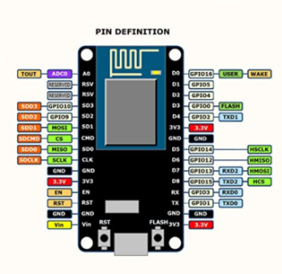
Excuse my ignorance here, which is the best pin for temp input and why? Again, this is all new to me. I have a 4.7k resistor across the data and 3.3V line of the temp probe. Admittedly the probe is bought off aliexpress and I’m hoping that is the issue. I’ve ordered some elsewhere, although they look identical. There wasn’t a wiring diagram - i used black for ground, red for 3.3 and yellow for data.
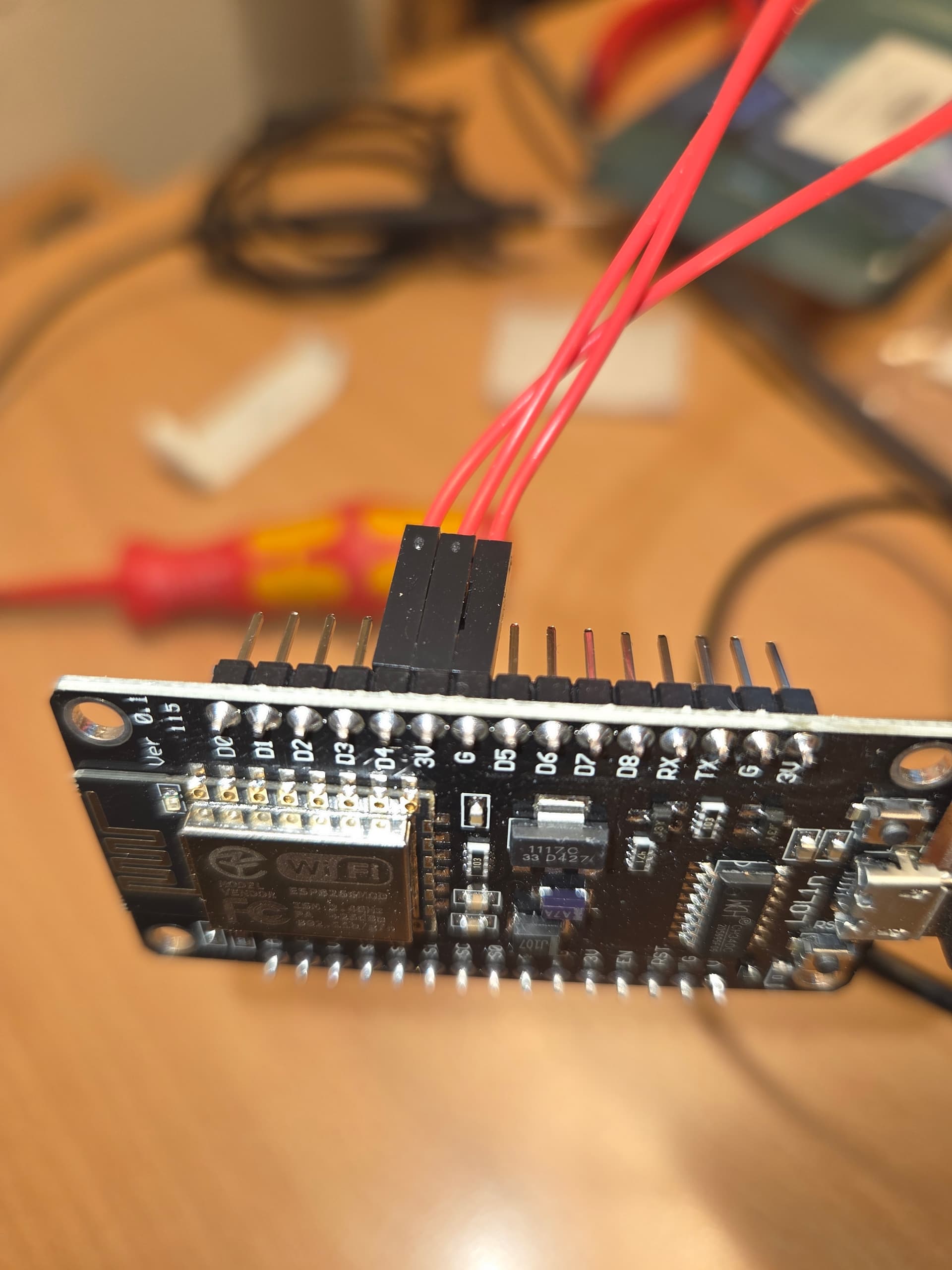
I have a node MCU chip and I connected the probe to D4 - GPI02. I attempted a different pin D2 - GPI04 with the same result. I tested the D4 pin and did see 3.3V on start up.
well D4 is already pulled up, but commonly internal pullup are weak so you just created a parallel that is still weak.
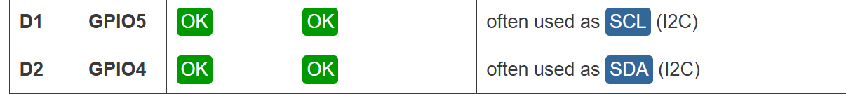
I’d try with a totally free GPIO (look at the table Tom posted above), but honestly if you have not used a very long cable DS18b20 sensors commonly works also with a weak pullup.
Check the connections again
D1/D2 are the most trouble free pins in general, D4 should be ok in this case as well though.
Your wiring description looks good, but are your wires well soldered?
You could post your code.
The data pins on both the master (ESP) and slave (temperature sensor) are open drain, i.e. they are switches that short to ground. Thus a pull up resistor is required to sense the drop in voltage when these pins are active. The size of the resistor is determined by the capacitance of the line and signalling timing. Recommended values are from 5K to 1K Ohms for short (1 meter) to long (~100s of meters) lines respectively.
The resistor can also be used to supply power to the slave device if it supports and is connected in parasitic mode (data and ground lines only). Not recommended that you complicate things this way unless absolutely necessary (i.e. you really can’t supply a power wire for some reason).
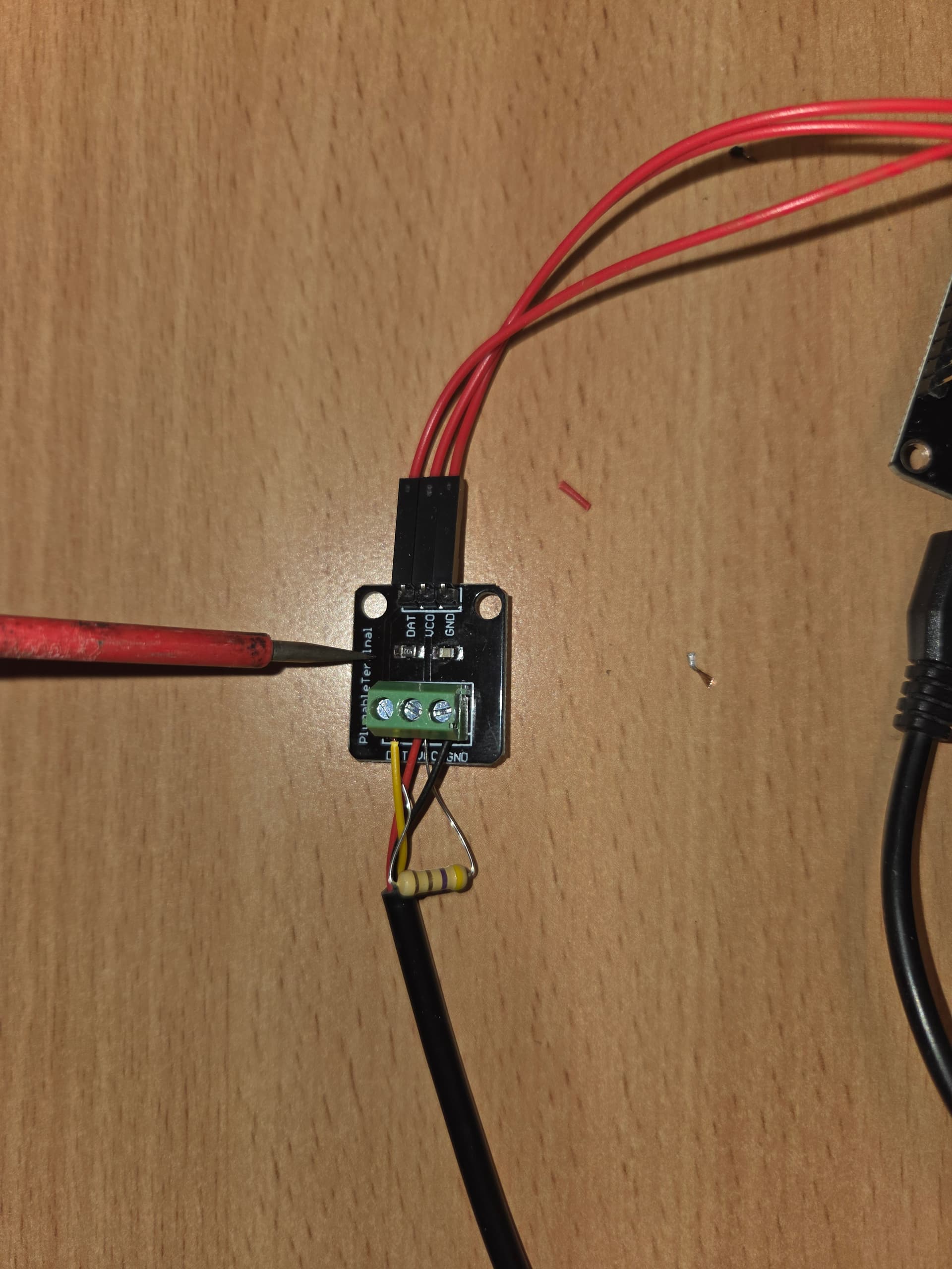
Hi Karosm, I have not soldered any connections, I have pin used pin connectors. The probe is connected to a small module allowing the probe to be terminated and the pin connectors connected. I have proven continuity from this termination point to the soldered side of the pin connector on the esp.
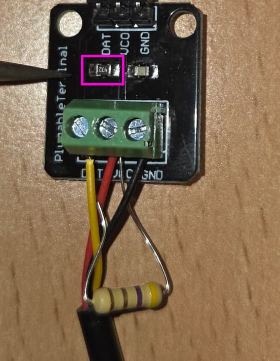
You don’t need the extra one in the screw terminals. It won’t be the cause of your issue but you can remove it for simplicity.
EDIT: actually it might be a problem. If that colour code is yellow - purple - gold - gold then it is a 4.7 OHM resistor (not K Ohm). If it is yellow - purple - brown - gold then it is a 470 Ohm resistor.
Both are very low values that the sensor may have trouble pulling to ground.