ESPHome + 2432S024C Display (ILI9341)

I have an issue getting ESP Home to run with an “ESP32 2432S024C” Touch Display.

The display uses ILI9341 and touch CST820.

The code snippets from the board manufacturer refer to the reset pin as “-1” but ESPHome obviously does not accept a “-1” pin:

I took the code snipped from the ESP Home documentation:

spi:
  clk_pin: 14
  mosi_pin: 13
  miso_pin: 12

color:
  - id: my_red
    red: 100%
    green: 3%
    blue: 5%

display:
  - platform: ili9xxx
    model: ili9341
    dc_pin: 2
    reset_pin: 1
    lambda: |-
      it.fill(COLOR_BLACK);
      it.fill(my_red);

But display stays black and ESP Home log says:

[10:31:06][W][component:214]: Component display took a long time for an operation (0.08 s).
[10:31:06][W][component:215]: Components should block for at most 20-30ms.
[10:31:07][W][component:214]: Component display took a long time for an operation (0.08 s).
[10:31:07][W][component:215]: Components should block for at most 20-30ms.

Ok those pin settings seems to work and displays an image:

color:
  - id: my_red
    red: 100%
    green: 3%
    blue: 5%
  - id: my_blue
    red: 5%
    green: 3%
    blue: 100%

spi:
 clk_pin: GPIO14
 mosi_pin: GPIO13
 miso_pin: GPIO12

image:
  - file: "test/test.jpg"
    id: my_image
    type: RGB24

display:
  - platform: ili9xxx
    model: TFT 2.4
    cs_pin: GPIO15
    dc_pin: GPIO2
    rotation: 90
    id: tft_ha
    lambda: |-
      it.fill(COLOR_BLACK);
      it.fill(my_red);
      it.line(0, 0, 50, 50);
      it.image(0, 0, id(my_image));

# Define a PWM output on the ESP32
output:
  - platform: ledc
    pin: 27
    id: gpio_27_backlight_pwm

# Define a monochromatic, dimmable light for the backlight
light:
  - platform: monochromatic
    output: gpio_27_backlight_pwm
    name: "Display Backlight"
    id: back_light
    restore_mode: ALWAYS_ON

… but the log still outputs this - is this ok?

[10:31:06][W][component:214]: Component display took a long time for an operation (0.08 s).
[10:31:06][W][component:215]: Components should block for at most 20-30ms.
[10:31:07][W][component:214]: Component display took a long time for an operation (0.08 s).
[10:31:07][W][component:215]: Components should block for at most 20-30ms.
1 Like

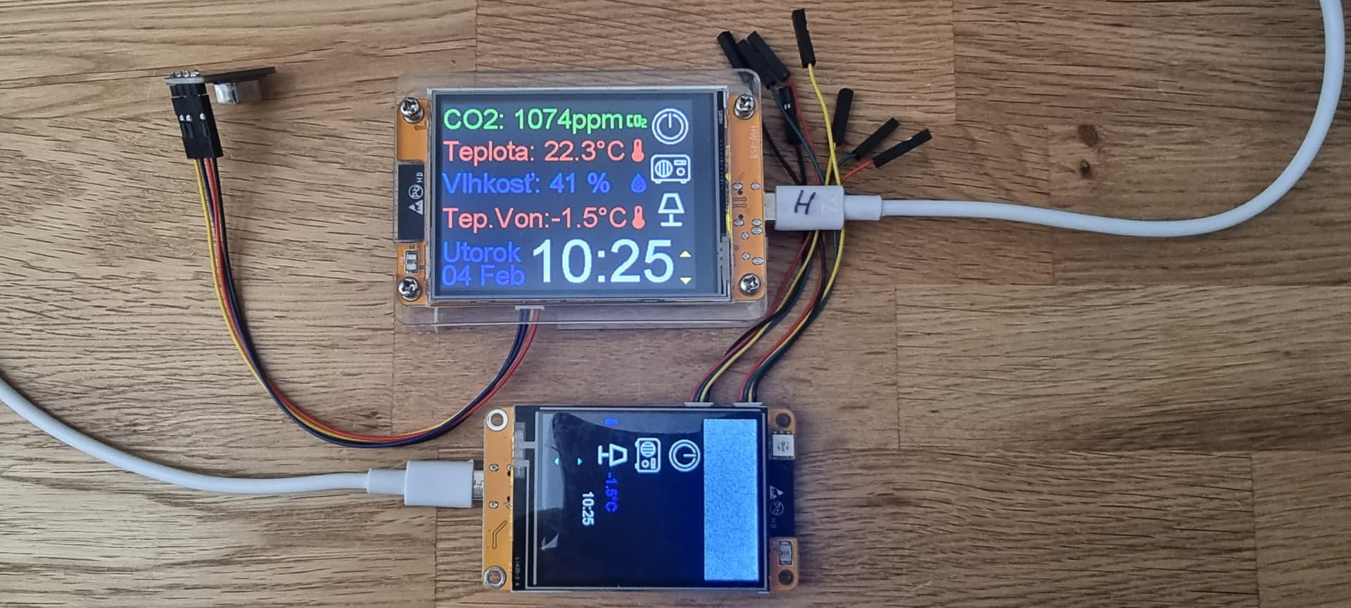
hi, does anyone have an esp32 2432s024c (C-USB) board working via ESPHome in Home Assistant? please yaml.The touch chip is on the xpt2046 board. thanks
Here is my test but non-working touch screen. yaml for ESP32-2432S024C (usb C)

i2c:
  sda: GPIO27  # Orig pôvodny 27 bol pre 2.8" LCD ale pre 2.4" I'll fix that after I enable touch.
  scl: GPIO22  # Orig pôvodny 22 bol pre 2.8" LCD ale pre 2.4" I'll fix that after I enable touch.
  scan: true
  id: bus_a

spi:
  - id: lcd
    clk_pin: GPIO14     # Orig gpio 14 for 2.8" LCD but for 2.4" ???
    mosi_pin: GPIO13  # Orig gpio 13 for 2.8" LCD but for 2.4" ???
    miso_pin: GPIO12  # Orig gpio 12 for 2.8" LCD but for 2.4" ???je
  - id: touch
    clk_pin: GPIO25     # Orig gpio 25 for 2.8" LCD but for 2.4" ???
    mosi_pin: GPIO32  # Orig gpio 32 for 2.8" LCD but for 2.4" ???
    miso_pin: GPIO39  # Orig gpio 39 for 2.8" LCD but for 2.4" ???

display:
  - platform: ili9xxx
    model: ILI9341
    spi_id: lcd
    cs_pin: 15       # Orig gpio 15 for 2.8" LCD but for 2.4" ???
    dc_pin: 2         # Orig gpio 2 for 2.8" LCD but for 2.4" ???
    rotation: 90 
    invert_colors: false
    update_interval: 5s  

touchscreen:
  platform: xpt2046
  spi_id: touch
  cs_pin: 33                # Orig gpio 33 for 2.8" LCD but for 2.4" ???
  interrupt_pin: 36      # Orig gpio 36 for 2.8" LCD but for 2.4" ???
  update_interval: 150ms  
  threshold: 400
  calibration:              # Setting about for 2.4 " ???
    x_min: 1000
    x_max: 3000
    y_min: 1000
    y_max: 3000
  transform:
    mirror_x: true
    mirror_y: false
    swap_xy: false

output:
  - platform: ledc
    pin: GPIO27            #  Orig gpio 21 for 2.8" LCD but for 2.4" is ok 27 ???
    id: former_led_pin
  - platform: ledc
    id: output_red
    pin: GPIO4             # Orig gpio 33 for 2.8" LCD but for 2.4" 33 is ok
    inverted: true
  - platform: ledc
    id: output_green
    pin: GPIO16         # Orig gpio 16 for 2.8" LCD but for 2.4" 16 is ok
    inverted: true
  - platform: ledc
    id: output_blue
    pin: GPIO17        # Orig gpio 17 for 2.8" LCD but for 2.4" 17 is ok
    inverted: true

light:
  - platform: monochromatic
    output: former_led_pin
    name: "Display Backlight"
    id: back_light
    restore_mode: ALWAYS_ON
  - platform: rgb
    name: LED
    id: led
    red: output_red
    green: output_green
    blue: output_blue
    restore_mode: ALWAYS_OFF`


So I managed to do it and created a working yaml for esp32 2432s024c (C-USB), so if anyone wants to they can use it :blush:.

i2c:
  sda: GPIO21  # Orig gpio 27 for 2.8" LCD but for 2.4" gpio 21
  scl: GPIO22   # Orig gpio 22 for 2.8" LCD but for 2.4" gpio 22
  scan: true
#  id: bus_a

spi:
  - id: lcd
    clk_pin: GPIO14     # Orig gpio 14 for 2.8" LCD but for 2.4" gpio 14
    mosi_pin: GPIO13  # Orig gpio 13 for 2.8" LCD but for 2.4" gpio 13
    miso_pin: GPIO12  # Orig gpio 12 for 2.8" LCD but for 2.4" gpio 12
#  - id: touch
#    clk_pin: GPIO25     # Orig gpio 25 for 2.8" LCD but for 2.4" no
#    mosi_pin: GPIO32  # Orig gpio 32 for 2.8" LCD but for 2.4" no
#    miso_pin: GPIO39  # Orig gpio 39 for 2.8" LCD but for 2.4" no

display:
  - platform: ili9xxx
    model: ILI9341
    spi_id: lcd
    cs_pin: 15       # Orig gpio 15 for 2.8" LCD but for 2.4" gpio 15
    dc_pin: 2         # Orig gpio 2 for 2.8" LCD but for 2.4" gpio 15
#    reset_pin: 3
    rotation: 180
    invert_colors: false
    update_interval: 5s  
    dimensions:
       height: 240
       width: 320

touchscreen:
  platform: xpt2046
  spi_id: touch
  cs_pin: 33                # Orig gpio 33 for 2.8" LCD but for 2.4" gpio 33
#  interrupt_pin: 36      # Orig gpio 36 for 2.8" LCD but for 2.4" gpio no
  update_interval: 150ms  
  threshold: 400
  calibration:              # Setting about for 2.4 " ???
    x_min: 200
    x_max: 3900
    y_min: 200
    y_max: 3900
  transform:
    mirror_x: true
    mirror_y: false
    swap_xy: false

output:
  - platform: ledc
    pin: GPIO27            #  Orig gpio 21 for 2.8" LCD but for 2.4" is ok 27 
    id: former_led_pin
  - platform: ledc
    id: output_red
    pin: GPIO4             # Orig gpio 33 for 2.8" LCD but for 2.4" gpio 4 is ok
    inverted: true
  - platform: ledc
    id: output_green
    pin: GPIO16         # Orig gpio 16 for 2.8" LCD but for 2.4" gpio 16 is ok
    inverted: true
  - platform: ledc
    id: output_blue
    pin: GPIO17        # Orig gpio 17 for 2.8" LCD but for 2.4" gpio 17 is ok
    inverted: true

light:
  - platform: monochromatic
    output: former_led_pin
    name: "Display Backlight"
    id: back_light
    restore_mode: ALWAYS_ON
  - platform: rgb
    name: LED
    id: led
    red: output_red
    green: output_green
    blue: output_blue
    restore_mode: ALWAYS_OFF

What pins are used for uart on the P1 bus for RX and TX? And how to set in yaml for Home Assistant Audio - speaker on GPIO 26. Thanks