I have a D1 mini connected to a 18650 battery. I would like to measure the voltage of the battery through the A0 pin on the D1 mini, but I’m not sure how to wire it. The A0 pin measures voltages between 0.0 - 1.0 volts and the 18650 outputs ~3.7 volts.
Can anyone point me in the right direction on how to wire the 18650 battery to the D1 mini and measure the battery voltage? I read this documentation: https://esphome.io/components/sensor/adc.html But I’m still not sure how to wire it all…
So the logic used is that A0 on D1 will output 3.3 V at max, if the measured voltage on A0 is say 2.97V then fair to say that battery level is 90% (2.97/3.3). Is this correct?
The maximum voltage that D1 can output is determined by its supply voltage i.e. 3.3V. (Vcc)
The input into A0 from the voltage divider is based on its supply voltage i.e. 3.7V and will always be a fraction of (Vbat), so yes your assumption is correct. Hope this clarifies.
Hi
The maximum output from the OP 18650 battery is 4.2V (for the nominal 3.7 V of what 18650 has).
The A0 pin is measuring the output of the battery not the output of the D1.
4.2 V would be enough to damage the D1 so you need to put a 220K Resistor between the battery and A0.
You will then need to multiply this by a factor to bring it up to 4.2 V when the 18650 if fully charged.
If you use ESPhome on the D1 you can put this factor in to the HTML for the ESPhome program to output directly as a sensor.
The 3.3 V output of the D1 shouldn’t change until battery is very low due to Lowdropout voltage regulator on the D1.
It looks like @bastero is using a voltage divider to drop the max 4.2 down to 3.3. Doesn’t sound like a good idea. I mean a terrible idea. Much better to use a LDL voltage regulator to bring battery voltage down to what the D1 uses. If you use a voltage divider to drop the voltage of the battery it will give a different voltage to power the D1 as the battery runs down. You want a constant voltage to the D1.
I look closer and I stand corrected. Appologies @bastero. The idea of not using voltage divider to power D1 from a battery still is a good one do you agree? Voltage divider fine for measuring battery voltage.
Out of interest, what resistor would you suggest between the + terminal of battery and A0 in the interests of not drawing much current from the battery but also not affecting the voltage reading much?
I would have thought the bigger the better. The math for the divider will be the same whether the resistors are large or small values, but the current draw (and battery wastage) will be smaller is the resistors are larger values.
Yes, I think ( as I’ve not got a background in electronics) that higher resistor values mean less current draw to the voltage measurement. I wonder then if you move up into mega ohm resistors then does the actual load (esp board) begin to affect the voltage reading to A0. I’m thinking of a reasonable compromise point that is generally accepted. In my setup I can detect about 5mv wobble which I have been putting down to the actual load. More than enough for my purpose. Just looking to learn more.
Let’s not forget that there is a Battery Shield for D1 mini on the market that has the necessary resistor, battery to A0 jumper and PH2.0 battery connector readily installed.
I am using the battery shield with the D1 mini but indeed it’s not very evident how to measure the voltage / % of the 18650. There is no information about it anywhere as of the moment of writing this. The shield sits on top, there’s no information on what to replace or connect or correct in order to get the information displayed. It is assumed that the battery power is to be read by pin0, because for what I see the value just remains invariable, but that’s just my personal experience. Can someone please give a guide about how to get the information on Home Assistant, and if there’s any modifications that have to be done to the battery shield itself or its connections? Thanks.
Or a bit more worked out if you want smoother readings and/or prefer voltage AND capacity percentage sensors in HA.
(Before someone shoots me for claiming that I measure capacity by measuring voltage: I am perfectly aware that this is always a rough estimate of capacity. But it is certainly fit for purpose.)
You can always ‘internal: yes’ one of them if you prefer.
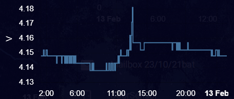
The short update_interval combined with the median filter level-out the very frequent measurement fluctuations.
The D1 mini goes then into deep sleep for 15 or 20 minutes and is back awake for 20 seconds to send its battery, WiFi strength, BME280 temperature and other values to HA.
The Throttle makes sure that there is only one value sent every 15 minutes (and not every 7 seconds) when the D1 is kept awake for OTA updates and also only one during the 20 seconds awake time.
A 18650 battery load lasts at least 2-3 months here with a BME280 attached. About a month with a soil moisture sensor.
No luck yet. Maybe our battery shield modules differ somehow, mine has only one jumper (J1) which opened is marked as 0.5A and closed as 1A, as a matter of fact if I close it the jumper, it won’t even start when connected. With it opened, the device works but the battery level will read constantly as 0V.