Hi everybody,
do any of you have experience designing custom boards and would help me get started for my ESPhome project? I want to create my own multisensor fitting my needs. Below is a minimalistic version on a (some) breadboard(s). It contains
- 1x PIR sensor (motion detection)
- 1x REED sensor (door/window state) via binary sensor
- 4x LED
- 1x Status LED (blue)
- 3x GPIO Switch
- red => door/window open
- green => door/window closed
- yellow => motion detected
- 1x TEMT6000 sensor (brightness / lux)

Obviously, this is just for testing purposes, so it doesn’t matter that it looks messy. However, I am currently trying to build a prototype that I can actually use, so it needs to
- fit into a mounting box
- be soldered to a board
- give me the option to replace parts (see below)
What will be different compared to the device above?
- additional reed sensor (as I want the states for two windows next to each other)
-
additional
BME280sensor for temperature, humidity, pressure - sensor being connected via MCP23017 I/O Expander so that I will have the option to connect more sensors without running out of PINs
In order to quickly be able to replace parts, both the nodeMCU v.1 and the MCP23017 are not soldered to the board itself, but rather plugged into fitting header pins that I previously soldered to the board.

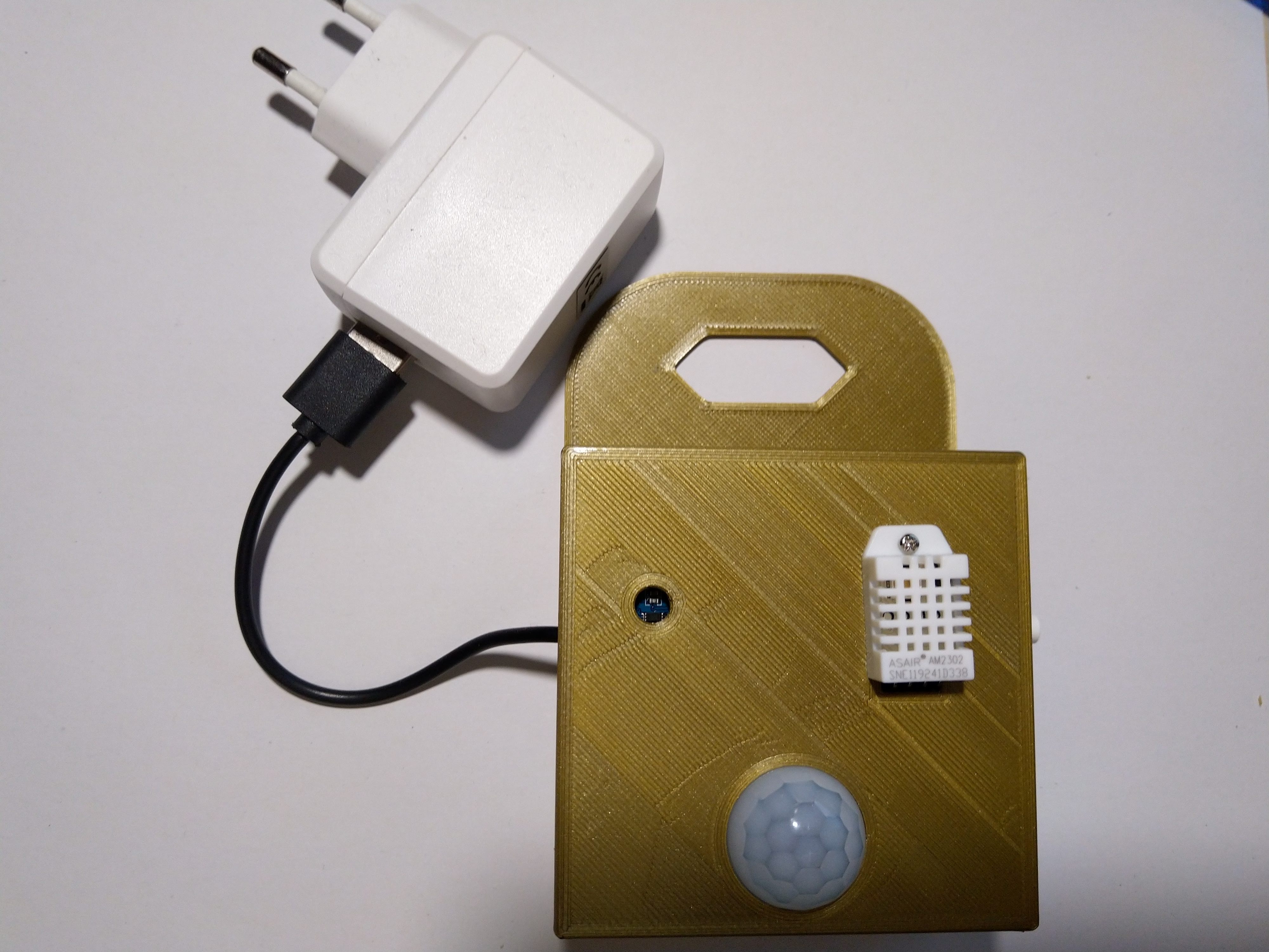
This is what my board currently looks like; I know, it is awful! That’s why I started this thread.


This is my code; after flashing, I see this is the debug output (via serial), so I can assume that I soldered things okay… otherwise it wouldn’t detect the device at 0x20.
[13:33:02][C][i2c:028]: I2C Bus:
[13:33:02][C][i2c:029]:   SDA Pin: GPIO14
[13:33:02][C][i2c:030]:   SCL Pin: GPIO12
[13:33:02][C][i2c:031]:   Frequency: 50000 Hz
[13:33:02][I][i2c:033]: Scanning i2c bus for active devices...
[13:33:02][I][i2c:040]: Found i2c device at address 0x20
substitutions:
  devicename: flur_oben
  upper_devicename: Flur Oben


esphome:
  name: $devicename
  platform: ESP8266
  board: nodemcuv2

ota:
  safe_mode: True
  password: much_secret
  port: very_port

api:

logger:
  level: debug

wifi:
  ssid: !secret wifi_name
  password: !secret wifi_password

web_server:
  port: 80
  auth:
    username: such_username
    password: very_secret_too

text_sensor:
  - platform: version
    name: "${upper_devicename} remote Version"
  - platform: wifi_info
    ip_address:
      name: "${upper_devicename} remote IP"
    ssid:
      name: "${upper_devicename} remote SSID"
    bssid:
      name: "${upper_devicename} remote BSSID"

i2c:
  - id: bus_a
    sda: D5
    scl: D6
    scan: True
I could work with this, but I would prefer not to; my soldering job is embarrassing even for a hobbyist such as myself. Usually I’d say I can do at least a decent job soldering things, but these pins are too close to each other and that makes it very difficult for me. I will keep working on this, but just so that I see how well my prototype works. For the actual devices I’ll want to use (which will be quite a bunch as I need one per window / door; even though not all of them need all those sensors from above, at least one per room does).
I need >30 of these around the house, so it would be so much easier to work with a template board that doesn’t require me to solder all connections over and over again…
Have any of you got experience creating custom boards and would be willing to help me out?
The finished board would require
- header pins for
nodeMCU - header pins for
MCP23017 - connections between the two devices (what is currently done via those red, yellow, black and orange wires by me in the images above)
- connections between the
MCP23017and a bunch of terminal screw headers and speaker terminals (for the reed sensors)
I currently only have two I/O terminal screw headers, but should probably just use those I pictured below, as the sensors usually require at least 3 pins (VCC, GND, DATA; or more). I am open to suggestions here as I don’t know what’s best practice.


I am using the free software Fritzing to create overviews of my projects (so that I’ll remember how to wire what without making mistakes when re-building things); this even has an option to show what the board would look like, but I have no idea how to go from there
My “overview” just to remember how to wire what

The supposed board
(

This is not a finished version of the multisensor I want to build as the MCP23017 is not included in the sketch. I just added it today and didn’t create a new file for it yet. Will work on that now. But how do I go from here?
Thank you in advance for any ideas