ESPHome multiple MCP23017?

Hi everybody,

can you please take a look at my code below? I am trying to connect multiple MCP23017 to a WeMos D1 Mini.
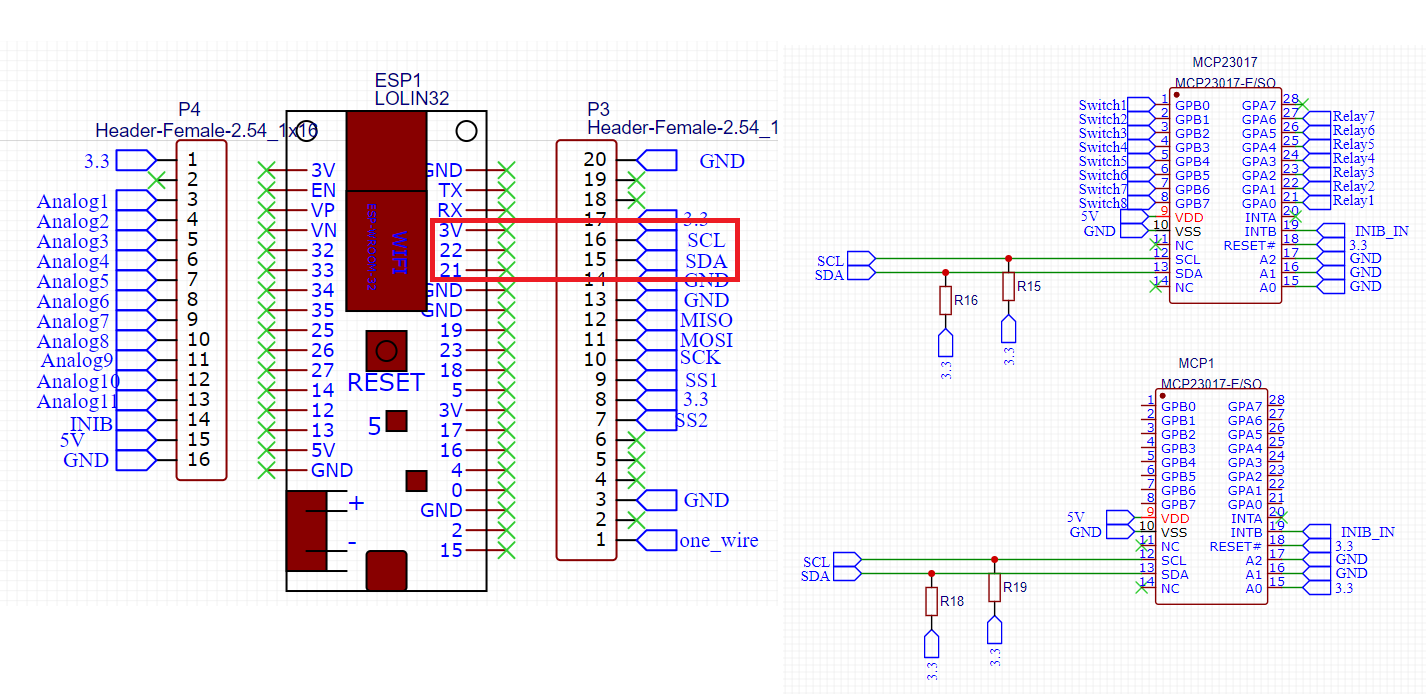
The wiring is

3V3 (MC) > VCC (#1)
GND (MC) > GND (#1)
D8 (MC) > SDA (#1)
D7 (MC) > SCL (#1)

VCC (#1) > VCC (#2)
GND (#1) > GND (#2)
D6 (MC) > SDA (#2)
D5 (MC) > SCL (#2)

Then there is an binary_sensor (in this case, a button) connected to each VCC and A0 per MCP23017 (it won’t work when I use B0).

However, currently, both button entities in Home Assistant will initially show as OFF (which is correct), but then switch to ON when I just press one of the buttons. I expected them to react to the corresponding MCP23017 individually.

Is this a code or a wiring issue? I assumed because I use different SDA/SCL pins on the D1 Mini, both MCP23017 could be on 0x20. I didn’t see anything in the docs for the MCP23017 that would allow me to use 0x20 on one, and 0x21 on the other.

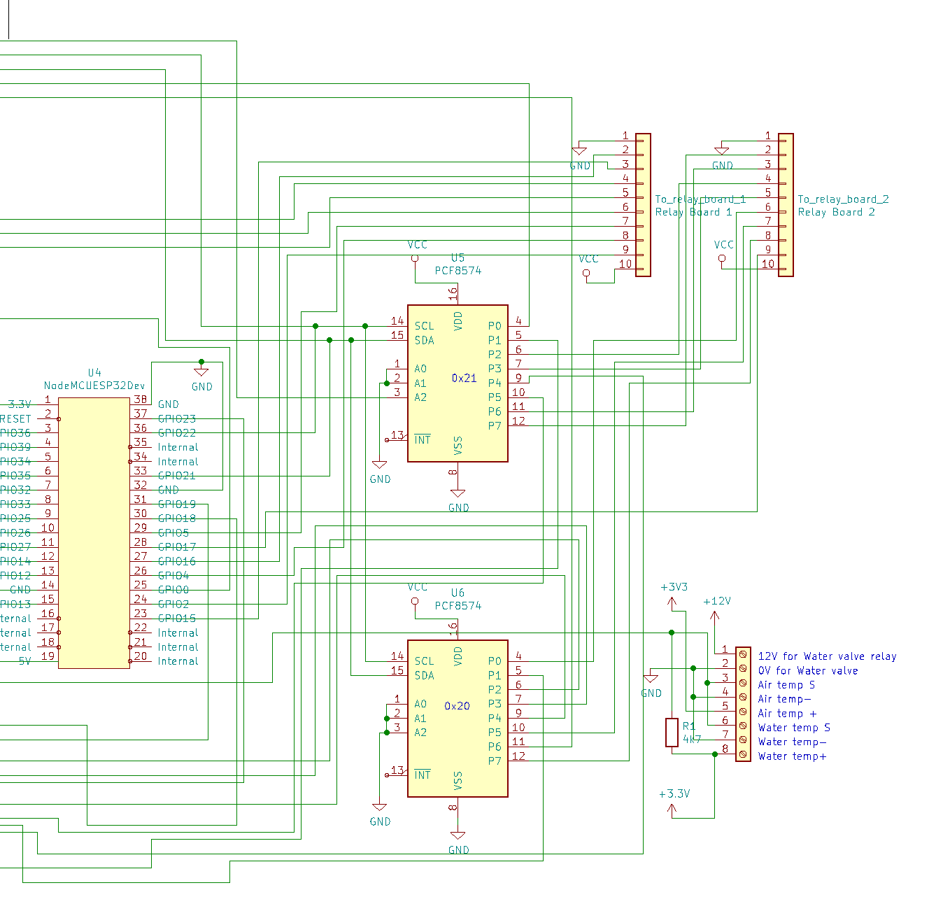
And: can I utilize even more than two MCP23017 on this one D1 Mini (or similar MC running ESPHome)? This project was supposed to provide 18 binary_sensors alone; 18 buttons would mean >2 individual MCP23017 devices. If possible, I’d even like to have additional LEDs, perhaps sensors, and tactile switch(es), so at the very least, I’d need those three MCP23017 running.

This is supposed to be a portable Home Assistant controller. It would be supposed to always be connected to power via USB cable; however, this cable would actually charge the power bank inside this box, which, in turn, would be connected to the WeMos D1 Mini. So you could move around with it a bit without losing connectivity, but eventually have to plug it in to make sure the power bank won’t die.

Thank you in advance for your ideas :slight_smile:

substitutions:
  devicename: holzbox
  upper_devicename: Holzbox
  platform: ESP8266
  board: d1_mini

esphome:
  name: $devicename
  platform: $platform
  board: $board

wifi:
  ssid: !secret wifineu_ssid
  password: !secret wifineu_pass
  use_address: $devicename.local

  # Enable fallback hotspot (captive portal) in case wifi connection fails
  ap:
    ssid: "${upper_devicename} Fallback Hotspot"
    password: !secret pw_accesspoint

captive_portal:

# Enable logging
logger:

# Enable Home Assistant API
api:
  password: !secret pw_api

ota:
  safe_mode: true # WICHTIG, falls mal was nicht klappt
  password: !secret pw_ota

web_server:
  port: 80
  auth:
    username: !secret user_http
    password: !secret pw_http

i2c:
  - id: bus_a
    sda: D8
    scl: D7
    scan: true
  - id: bus_b
    sda: D6
    scl: D5
    scan: true


mcp23017:
  - id: 'mcp23017_hub'
    address: 0x20
  - id: 'zweiter_hub'
# I also tried address: 0x21 here
    address: 0x20
  
binary_sensor:
  - platform: gpio
    name: "MCP23017 Pin #1"
    pin:
      mcp23017: mcp23017_hub
      # Use pin number 1
      number: 0
      # One of INPUT or INPUT_PULLUP
      mode: INPUT_PULLUP
      inverted: true
  - platform: gpio
    name: "MCP23017 ZWEI Pin #1"
    pin:
      mcp23017: zweiter_hub
      # Use pin number 1
      number: 0
      # One of INPUT or INPUT_PULLUP
      mode: INPUT_PULLUP
      inverted: true

You should configure both your mcp23017 components to use the I2C bus they’re attached to:

mcp23017:
  - id: 'mcp23017_hub'
    i2c_id: bus_a
    address: 0x20
  - id: 'zweiter_hub'
    i2c_id: bus_b
    address: 0x20
1 Like

changing addresses is used when all mcp23017 are connected under same SDA & SCL pins then you need change address + solder A0 A1 A2 pins base on address (0x20 is default address, 0x21 needs one solder to VCC) …

or use multile SDA & SCL and make it as Oxan said …

BR

Antra

1 Like

I use two pcf8574 which, I believe do the same.

I have then configured as below.

i2c:
  sda: 21
  scl: 22

pcf8574:
  - id: 'expander_1'
    address: 0x20
    pcf8575: False
  - id: 'expander_2'
    address: 0x24
    pcf8575: False

and then used thus:

 - platform: gpio
    pin: 
      pcf8574: expander_1
      number: 5
      mode: OUTPUT
    name: "Ozone air"
    inverted: True
    icon: mdi:air-filter
    restore_mode: RESTORE_DEFAULT_ON
    id: ozone_air

Hope that is of some help.

1 Like

Thanks, everybody. I just got around to testing this now. For some reason, as soon as I connect the second MCP23017 with these settings, nothing will work (neither the first button, that first would control both entities, nor the second one).

I tried chaining them via the ESPs (switched to WROOM-32) power, using an external (3V3) power source, but nothing so far.

this is my schematic which i using on my own board for control HA. Code is same as mentioned ashcott. Hope its help

1 Like

Thanks, everybody. It seems like I got it working now.

@Antrac1t how do you address the GPA/GPB buttons? When I use a number only, it will always just work with GPA. I tried using GPA0 etc., but that will throw an error about that PIN not existing.

something like this

switch:
 - platform: gpio
    name: "valve_kitchen"
    id: valve_kitchen
    restore_mode: always off
    pin:
      mcp23xxx: mcp23017_hub
      number: 0
      mode: OUTPUT
      inverted: True

I received a DM from @Sunil asking for the connections to the expander. Here it is below:

Thank you very much. Greatly appreciated. Unfortunately, the left side has cut off, so will you be able to re-post it please.

You have everything I have there that pertains to the expanders and inputs and outputs. The rest is specific to my application and not relevant here.

What other parts are you struggling with?

So does that mean that A0 is for INPUT and B0 is for OUTPUT? I am using it like this

    name: "MCP23017_01 Pin A7"
    pin:
      mcp23xxx: mcp23017_hub_01
      number: 7
      mode: INPUT_PULLUP
      inverted: true

This will default to A7, no matter what I do. Even if there is nothing connected to A7 but I switch to B7, it will not work when just specifying number: 7. This is kinda confusing.

nope, you can use A and B for input or output … btw put under i2c the scan part and check if esp find your MCP, if yes then result should be like this

[15:16:52][I][i2c:033]: Scanning i2c bus for active devices…
[15:16:52][I][i2c:040]: Found i2c device at address 0x20

i2c:
  sda: 21
  scl: 22
  scan: True

Pin numbers are from 0 to 15. 0 to 7 are Ax, from 8 to 15 are Bx pins.

1 Like

I have been using the mcp23017 with Home Assistant with no problem. Was going to make changes to file and was prompted to update ESPHome; when I tried to update received the following message:
‘mcp23017:’ has been removed from the pin schema in 1.17.0, please use ‘mcp23xxx:’.
pin:

Any suggestions as to how proceed?
Thanks,
Bob

You can replace mcp23017 in your configuration with mcp23xxx. Just change the literal string and try again, it should work.

That was easy, and it worked. Thanks.