At a first look, it seems to me that it provides a REST API and MQTT. So it should be no problem to include it in HA via REST sensor or MQTT, or did I understand anything wrong?
rather my ignorance ![]() I will try.
I will try.
Digging into the spec sheet for the chip, that interrupt pin is used for multiple uses.
-
If the noise floor is too high, it sends an INT and LEAVES IT SET until the noise floor is normal. That turns out to crash the software, or at least cause the ESP do disconnect from wifi, because it’s so busy servicing that interrupt that nothing else can run. Hint, don’t set your noise floor value too low or you’ll need to reflash using a cable.
-
If the spike noise exceeds the threshold, it sends an INT and we get the suggestion to raise the spike rejection value. The INT is cleared when the INT Register is accessed, so this just spams the log but doesn’t crash the program. Configuring mask_disturber: true turns this INT off so you don’t see it. Other than the hardware having to process a lot of spikes in the detector, I’m not sure how serious it is.
-
If the hardware, after establishing the noise floor, and filtering out spike, finally sees enough events in a 15min sliding window, it sends an INT with the Storm Detected reason. This INT is not just a lightning strike notification, even when set to 1, because some spikes might fool the hardware enough to be classified as lightning. It’s actually the final filter and should probably be set to 5 or 9.
So, get the noise floor wrong and the board just goes into a coma. Set spike rejection too low and you risk fooling the storm detection. Use a lightning threshold > 1 to filter out a few more of the worse spikes and only let the actual lightning strikes accumulate in the detector.
I really wish those variables were available at run time, I’d like to create a slider component to vary them on the fly instead of having to change/compile/download each test setting change.
Just my 2 cents worth of opinion. 
Back when I tested that thing, I was playing with these 3 values for days trying all kind of combinations, those that seemed ‘logical’ and also those that didn’t, including testing the value extremes. Nothing worked. Not a single combination gave any kind of meaningful results.
I first tested it using the SparkFun lib. When it didn’t work, I rewrote the low level code myself for direct register access to the chip. Same disappointing results.
Then I realized I was wasting way to much time on that thing for the value it would bring, even if it ended up magically working somehow.
My current focus is on the noise level of the circuit. I stuck a scope on the INT and several other pins to track what was going on. Just after the INT hit, I could see CS trigger as the software read the chip, then saw a silly amount of noise on the ground pin, like the ESP was inducing noise into the power bus, probably as the program woke up wifi to log and send the results to HA.
The ESP has always been an extremely noisy chip. I did not use one, I used an Arduino with an ATmega328 CPU and without any RF communication. The power and ground lines were clean and so were the com lines for SPI. I used battery power to keep any kind of SMPS switching noise away from the AS. I used shielded cables and put the MCU in a grounded metal case. I positioned the entire thing almost a kilometer away from any electronics to remove the possibility of interference and induced noise.
None of that made any kind of difference. The thing did not work one single time.
Oh, i read it just now… Could save me money. Tried to get the sensor working first on i2c but it’s just not detected by the esp32. Not tested with spi.
Also tried to get it working with tasmota without succes. But i read on the instructions there that there could be wrong capacitors installed on the module. Quote from the instructions:
"“Some type of this sensor have wrong capacitors (100pF and 1000pF) installed and the calibration fails. The correct caps are 680pF and 270pF.” "
Good news everyone! I (think) i got my AS3935 working with a ESP8266 and ESPHome! It’s on inhome setting inhome very sensitive but on outdoors setting and electronic gaslighter it got values when i do it near the sensors.
How did i got it working?
With I2C on the ESP8266 and this pinout:

And this template with the ''All Sensors" Tasmota version.
{"NAME":"AS3935 Template","GPIO":[1,1,1,1,640,608,1,1,1,1,4672,1,1,1],"FLAG":0,"BASE":18}
Sorry if it’s not allowed to post something about Tasmota here in ESPHome. I will now try to get it working on ESPHome. But makes me just happy that the whole sensors looks like it works. Need also to wait to a thunderstorm. 
2 Likes
my sensor is working. Instructions on how to do it, but in Slovak.
Working meaning it detected a lightning strike that actually happened in a thunderstorm? Or do you mean working as, communication works? The first would be really interesting.
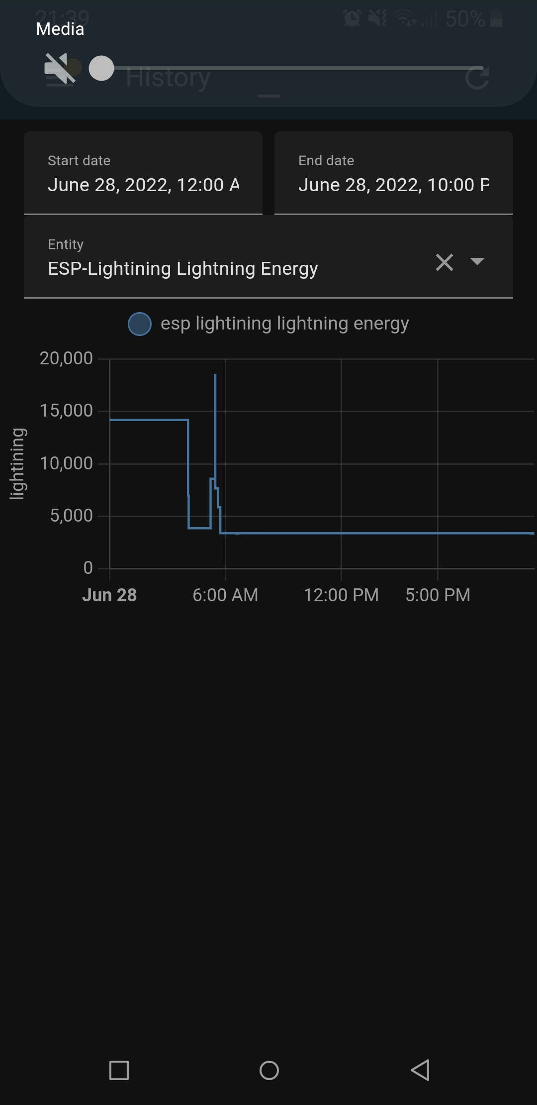
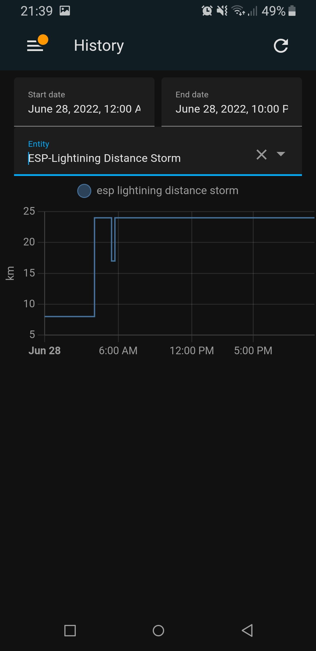
The first one. This sensor really works to detect lightning up to 25 km. I am sending the history 4 days ago we had a storm.
I am not proficient in English, otherwise I would make a detailed tutorial.
But probably the most important:
- position of the sensor lying down (horizontally).
- Connection in SPI.
- 1-2m from esp,
- powered by battery,
- located in exteriors.
especially the setting. the rest is in the link above
as3935_spi:
  cs_pin: GPIO15 #D8
  irq_pin: D1
  indoor: false
  noise_level: 2
  spike_rejection: 4      # Default 2
  lightning_threshold: 1
  mask_disturber: false
  div_ratio: 0
  capacitance: 5
  watchdog_threshold: 2
# Example lightning and energy sensor
It works like charm also on i2c. Last thunderstorm was a few days ago but i need to say that i don’t know how to configure it perfect. But it’s shure it can work. It detects almost all lightning.

Hmm, that could be my issue. Need to check.
in the vertical position, the sensor detected bad messages. That’s why it’s in horizontal.
tiimsvk, I tried to do the same, using the code from that CZ forum, it only gave me massive errors in esphome,
Number increment gave me an error not such function with the name
the meteo booelan gave an error that was not named it came up at the top of esphome in the editor and it showed a tiny empty error bubble without anything in it?!
Do you have a code that works in esphome and please would you share, please
this is my last code, code is valid.
but I am planning big changes regarding battery consumption … not only for this project
substitutions:
  friendly_name: ESP-Lightining
  device_name: esp-lightining
  device_description: "Lightining sensor CJMCU AMS AS3935 (https://www.homeassistant-cz.cz/viewtopic.php?f=56&t=379&p=3711#p3711), Deep Sleep and internal meteoalarm integrate"
  created_by: "StudioTiiM 2022"

#-------------------------------------------
# ESP Main settings
#-------------------------------------------
esphome:
  name: esp-lightining
  on_boot:
    priority: -150.0
    then:
      - component.update: batlevel
      - component.update: signal

esp8266:
  board: d1_mini_pro

# Enable logging
logger:
# level: warn

mqtt:
  broker: '192.168.31.212'
  username: !secret mqtt_username
  password: !secret mqtt_password
  discovery: true
#  discovery_retain: false
  birth_message:
    topic: $device_name/status
    payload: online
  will_message:
    topic: $device_name/status1
    payload: offline
  on_message:
##OTA UPDATE
#    - topic: $device_name/ota_mode
#      payload: 'ON'
#      then:
#        - deep_sleep.prevent: deep_sleep_component
#        - logger.log: "OTA blocking deep sleep"
#    - topic: $device_name/ota_mode
#      payload: 'OFF'
#      then:
#        - logger.log: "OTA finished run deep sleep"
#        - deep_sleep.allow: deep_sleep_component


#METEOALARM HASSIO SENSOR
    - topic: $device_name/meteoalarm_safe
      payload: 'OFF'
      then:
        - deep_sleep.prevent: deep_sleep_component
        - logger.log: "meteoalarm unsafe or ota"
    - topic: $device_name/meteoalarm_safe
      payload: 'ON'
      then:
        - logger.log: "meteoalarm safe or ota finished"
        - deep_sleep.allow: deep_sleep_component

deep_sleep:
  id: deep_sleep_component
  sleep_duration: 800s
  run_duration: 30s

ota:
  safe_mode: false

wifi:
  ssid: !secret wifi_ssid
  password: !secret wifi_password
  manual_ip:
    static_ip: 192.168.31.121
    gateway: 192.168.31.1
    subnet: 255.255.255.0
  fast_connect: True
#  power_save_mode: high

  # Enable fallback hotspot (captive portal) in case wifi connection fails
  ap:
    ssid: "Esp-Lightining Fallback Hotspot"
    password: "passlightining"

captive_portal:

spi:
  clk_pin: GPIO14 #D5
  mosi_pin: GPIO13 #D7
  miso_pin: GPIO12 #D6
# Example configuration for SPI (decide for one!)
as3935_spi:
  cs_pin: GPIO15 #D8
  irq_pin: D1
  indoor: false
  noise_level: 2
  spike_rejection: 3      # Default 2
  lightning_threshold: 1
  mask_disturber: false
  div_ratio: 0
  capacitance: 5
  watchdog_threshold: 2
# Example lightning and energy sensor
sensor:

##BATTERY
  - platform: adc
    pin: A0
    name: "${friendly_name} Battery Voltage"
    accuracy_decimals: 3
    update_interval: 10s
    filters:
      - multiply: 16.75
      - median:
          window_size: 7
          send_every: 4
          send_first_at: 1
    icon: mdi:battery
    id: batlevel
    internal: true
    device_class: battery
    entity_category: diagnostic
    on_value:
      then:
        - component.update: battery

  - platform: template
    name: "${friendly_name} Battery"
    id: battery
    unit_of_measurement: "%"
    accuracy_decimals: 0
    device_class: battery
    entity_category: diagnostic
    filters:
      - calibrate_linear:
          - 2.8 -> 0
          - 4.20 -> 100
      - filter_out: 0.0
      # No value lower than 0
      - lambda: 'return max((float)0.0, x);'
      # No value greater than 100
      - lambda: 'return min((float)100.0, x);'
    lambda: |-
      return (id(batlevel).state);
    update_interval: never
    icon: mdi:battery

##AS3935
  - platform: as3935
    lightning_energy:
      name: "${friendly_name} Lightning Energy"
      unit_of_measurement: "lightining"
      icon: mdi:lightning-bolt-outline
      accuracy_decimals: 0
      on_value:
        then:
          - number.increment: light_counter
    distance:
      name: "${friendly_name} Distance Storm"
      icon: mdi:access-point
      accuracy_decimals: 0
#daily counter
#  - platform: total_daily_energy
#    name: "${friendly_name} Lightning Daily"
#    power_id: light_counter_temp
#    icon: mdi:lightning-bolt-circle
#    filters:
#        # Multiplication factor from W to kW is 0.001
#      - multiply: 60
#counter
  - platform: template
    name: "${friendly_name} Lightning Counter"
    id: light_counter_temp
    lambda: |-
      return (id(light_counter).state);
    unit_of_measurement: "pcs"
    accuracy_decimals: 0
    icon: mdi:lightning-bolt-circle
#    internal: true

# Wifi signal
  - platform: wifi_signal
    name: "${friendly_name} Signal"
    id: signal
#    update_interval: 10s

number:
  - platform: template
    name: "${friendly_name} Lightning Counter number"
    optimistic: true
    min_value: 0
    max_value: 1000
    step: 1
    id: light_counter
    internal: true

binary_sensor:
  - platform: as3935
    name: "${friendly_name} Storm Alert"
    icon: mdi:flash-alert-outline

switch:
##RESTART ESP
  - platform: restart
    name: "${friendly_name} Restart"

time:
  - platform: sntp
    id: esptime
    timezone: "Europe/Bratislava"
Thank you, it is the code i tried to use.
Alas I get two errors that will not go away, one is with the number increment, the other is the meteo.
I took out everything, only the bare minimum battery is not needed, meteo not needed, mqtt not used, no deep sleep, and taking out the counter, and by doing that the detector works
There was no other option for it rained errors had I not dome that.\
This is what is left, which works, counters I made in HA.
spi:
  clk_pin: GPIO14 #D5
  mosi_pin: GPIO13 #D7
  miso_pin: GPIO12 #D6
# Example configuration for SPI (decide for one!)

as3935_spi:
  cs_pin: GPIO15 #D8
  irq_pin: D1
  indoor: false
  noise_level: 2
  spike_rejection: 4      # Default 2
  lightning_threshold: 1
  mask_disturber: false
  div_ratio: 0
  capacitance: 5
  watchdog_threshold: 2
# Example lightning and energy sensor


sensor:

  - platform: as3935
    lightning_energy:
      name: "${friendly_name} Lightning Energy"
      icon: mdi:lightning-bolt-outline
    distance:
      name: "${friendly_name} Distance Storm"
      icon: mdi:access-point

  - platform: wifi_signal
    name: "${friendly_name} - WiFi Signal"
    update_interval: 300s

binary_sensor:
  - platform: as3935
    name: "${friendly_name} Storm Alert"

switch:
##RESTART ESP
  - platform: restart
    name: "${friendly_name} Restart"

text_sensor:
  - platform: wifi_info
    ip_address:
      name: "${friendly_name} - IP"
I used the example above, it works BUT I was still getting flooded with
–Disturber was detected - try increasing the spike rejection value!–
even with spike_rejection: 11
so I tried this
wifi:
  ssid: "xxxx"
  password: "xxxx"
  output_power: 9 #8.5-20
  power_save_mode: HIGH #HIGH NONE LIGHT
  fast_connect: true
and now I can use spike_rejection: 4 and not get any -Disturber was detected- at all even with the sensor and the esp module close on the same PCB
1 Like
my sensor and mcu are 1m apart… I will also post the new code on github tomorrow and give the link here
EDIT:
https://github.com/tiimsvk/Esphome-Franklin-Lightining
I will add some photos.
Plus it’s in testing stage…waiting for the storm.
I can confirm the AS3935 works. I have one connected to a Wemos D1 mini with BMP280 an a LUX sensor running for over a year. The AS3935 is connected via SPI, the rest via I2C including a display.
It detects most strikes quite accurate. I has some false detections from a starter of a fluorescent tube.