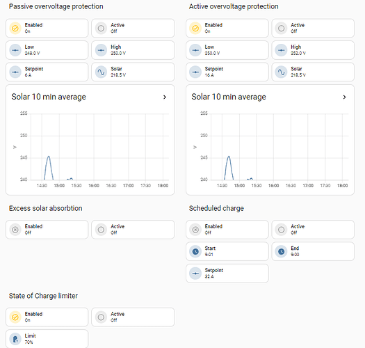
By far the most complex automation I have running is for my EVSE (EV charger) control. Combining the solar inverter integration (SMA), the EVSE integration (Wallbox), EV integrations (Polestar, Fiat, MG4) and a few other bits and pieces to provide:
- Scheduled charge
- State of Charge limit
- Excess solar power absorption
- Over-voltage protection
- Under-voltage protection
I will first describe the what for these functions, I will add the how and details later:
Scheduled charge
Both the Polestar and the Wallbox allow to set a scheduled charge. But of course it is more convenient to be able to set the schedule from within HA. I only use it in combination with the other functionality to make sure a car is charged the next day if needed.
State of Charge limit
Polestar recommends not to charge to 100% SoC to extend the battery life. Unfortunately the limit can only be set in the car, not from the app. This function allows me to set the limit from HA. I usually have it set at 80%, unless I really need the extra range.
Excess solar power absorption
Often exporting excess power is not attractive, a home battery can help to limit your export, an EV has a nice big battery to use for excess solar absorption as well. I’m lucky enough to be on net metering, so I don’t really have a benefit from this, but I’m future proof.
Over-voltage protection
When there is too much solar power generation the power network cannot cope and inverters start shutting down. Many people will not even realize, but it is a lost opportunity of course. In my neighborhood this is a serious issue, many large new installations on a dated network. On a sunny day I can avoid a dozen shutdown events as long as there is a car ready to charge.
Under-voltage protection
As much a dated power network causes over-voltage shutdowns it can also lead to severe under-voltage. With the many new solar installations also came many new EVs to the neighborhood. When the sun is down and people start charging their cars the mains voltage collapses. To at least not make it worse this function can limit the EV charging power.
The five functions work in concert. They can be enabled and have their parameters set from the management dashboard. But for day-to-day use this is too complicated. So I came up with three charging modes; ‘Whenever’, ‘Tomorrow’ and ‘Now’.
In ‘Whenever’ mode the excess solar absorption, the over- and under-voltage protection, and the SoC limit functions are active (if enabled), but the car is only charged as needed for that functionality.
In ‘Tomorrow’ mode the schedule function also becomes active to assure the car will be charged to the SoC limit in the morning.
In ‘Now’ mode the car will charge at the maximum charge current to charge asap to the SoC limit.
The automation runs every 12 seconds, checks if indeed the charger is happily communicating with a car and then evaluates all functions in order of priority to set the charger pause/resume and the charger current limit.
OVERVOLTAGE PROTECTION
The overvoltage protection helps to prevent the solar inverter from shutting down when the grid gets overloaded on a sunny day. According to the rules here, the inverter must shut down when the 10 min. average of the mains voltage (measured at the inverter) reaches 253 Volt RMS. Charging a car (pushing less onto or even drawing current from the net) affects the voltage delta between the street and the inverter. It is matter of keeping the inverter voltage below the 253V threshold until the neighbor’s solar systems start shutting down. It is like running from a bear, you only need to be faster than your friend.
The overvoltage protection automation has two stages, a passive protection and an active protection. When the connected vehicle is not charging, the initiation of a charge is too slow to correct. So the passive overvoltage protection kicks in at 250V at 6A and stops again at 245V (on/off controller with 5V hysteresis). The active overvoltage protection kicks in at 252V, stepping up the charge current with 1A every 12s loop as long as the voltage is higher than 252 V, keeping the charge current where it is when the voltage is between 252V and 250V, and stepping the charge current down when the voltage is below 250V (integrating controller with 2V hysteresis). The controllers use the 10 min average voltage at the solar inverter. The thresholds and set values can be changed from my management dashboard.
UNDERVOLTAGE PROTECTION
Undervoltage is a real issue in my neighborhood. When the sun goes down, people return home from work and start charging EVs and cooking, it can get real bad.
The undervoltage protection function monitors the mains voltage. If the voltage drops below 195V rms is starts limiting the charge current, similar to the overvoltage protection it step down 1A every 12s loop as long as the voltage is below 195V. When the voltage reaches 200V it start stepping the current up again (integrating controller with 5V hysteresis). Here too the thresholds can be changed from the management dashboard.

The undervoltage protection at work:
TO BE CONTINUED


