Fan controller

@mulcmu Thanks for the board design idea!

How I should configure ESP home to get fan entity?

  • Fan entity
    – On / Off
    – Speed - Slow, Medium, High

Have a look at this post. I think this is what your looking for.

1 Like

I would just use some buttons to control the fan instead of a fan entity, but that’s my preference. Basically you need to setup output pins to control each relay and then configure the relay states to get the right speed energized. The fan implementation @Blacky linked above looks superb if you want a fan entity.

output:
  - platform: gpio
    pin: 15
    id: relay1    
  - platform: gpio
    pin: 16
    id: relay2   
  - platform: gpio
    pin: 17
    id: relay3

button:
  - platform: template
    name: "Off"
    on_press:
      - logger.log: Off Pressed
      - output.turn_off: relay1
      - output.turn_off: relay2
      - output.turn_off: relay3
  - platform: template
    name: "Low"
    on_press:
      - logger.log: Low Pressed
      - output.turn_on:  relay1
      - output.turn_off: relay2
      - output.turn_off: relay3      
  - platform: template
    name: "Med"
    on_press:
      - logger.log: Med Pressed
      - output.turn_on: relay1
      - output.turn_on: relay2
      - output.turn_off: relay3      
  - platform: template
    name: "High"
    on_press:
      - logger.log: High Pressed
      - output.turn_on: relay1
      - output.turn_on: relay2
      - output.turn_on: relay3      

You have to make sure you only put power onto 1 speed at a time as per your wiring diagram above. See in the link above and use the “interlock” to ensure this happens or you will let the smoke out.

The fan motors have 4 speeds

@mulcmu, I have merged configs to get fan entity, please have a look.

Will it keep state after ha reboot?
Is it hard to add one more speed?

esphome:
  name: games_room_fan
  platform: ESP32
  board: d1_mini

wifi:
  ssid: !secret wifi_ssid
  password: !secret wifi_password
  manual_ip:
    static_ip: 192.168.0.132
    gateway: 192.168.0.1
    subnet: 255.255.255.0
  
api:

logger:

web_server:
#  port: 80

ota:
  password: !secret ota_password

binary_sensor:
  - platform: status
    name: "Fan Status"

switch:
  - platform: gpio
    pin: 15
    name: "Games Room Fan Speed 1"
    id: speed1
    interlock: [speed2, speed3]
  - platform: gpio
    pin: 16
    name: "Games Room Fan Speed 2"
    id: speed2
    interlock: [speed1, speed3]
  - platform: gpio
    pin: 17
    name: "Games Room Fan Speed 3"
    id: speed3
    interlock: [speed1, speed2]

output:
  - platform: template
    id: custom_fan
    type: float 
    write_action:
      - if:
          condition:
            lambda: return ((state == 0));
          then:
            # action for off
            - switch.turn_off: speed1
            - switch.turn_off: speed2
            - switch.turn_off: speed3
      - if:
          condition:
            lambda: return ((state > 0) && (state < 0.33));
          then:
            # action for speed 1
            - switch.turn_off: speed2
            - switch.turn_off: speed3
            - switch.turn_on: speed1
            
      - if:
          condition:
            lambda: return ((state > 0.33) && (state < 0.66));
          then:
            # action for speed 2
            - switch.turn_off: speed1
            - switch.turn_off: speed3
            - switch.turn_on: speed2
            
      - if:
          condition:
            lambda: return ((state > 0.66));
          then:
            # action for speed 3
            - switch.turn_off: speed1
            - switch.turn_off: speed2
            - switch.turn_on: speed3

fan:
  - platform: speed
    id: gamesroomfan
    output: custom_fan
    name: "FCU Fan"
    speed_count: 3

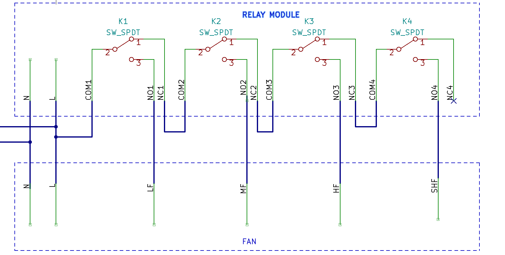
The schematic I posted above had the relays wired differently than the linked post. The linked post is a bit more intuitive as one and only one relay is energized for each fan speed. To wire the 4th relay to LF this would be the arrangement:

HA reboot should not impact the fan state. It would keep running at current speed.

Fan state after ac power loss to fan or esp reboot is controlled by fan: restore_mode
@mulcmu
It will use the same relay right?
How to switch fan off with 4 speeds?
It seems like fan is always on based on design.

Is it going to work?

esphome:
  name: games_room_fan
  platform: ESP32
  board: d1_mini

wifi:
  ssid: !secret wifi_ssid
  password: !secret wifi_password
  manual_ip:
    static_ip: 192.168.0.132
    gateway: 192.168.0.1
    subnet: 255.255.255.0
  
api:

logger:

web_server:
#  port: 80

ota:
  password: !secret ota_password

binary_sensor:
  - platform: status
    name: "Fan Status"

switch:
  - platform: gpio
    pin: 15
    name: "Fan Speed 1"
    id: speed1
    interlock: [speed2, speed3, speed4]
  - platform: gpio
    pin: 16
    name: "Fan Speed 2"
    id: speed2
    interlock: [speed1, speed3, speed4]
  - platform: gpio
    pin: 17
    name: "Fan Speed 3"
    id: speed3
    interlock: [speed1, speed2, speed4]
  - platform: gpio
    pin: 18
    name: "Fan Speed 4"
    id: speed4
    interlock: [speed1, speed2, speed3]

output:
  - platform: template
    id: custom_fan
    type: float 
    write_action:
      - if:
          condition:
            lambda: return ((state == 0));
          then:
            # action for off
            - switch.turn_off: speed1
            - switch.turn_off: speed2
            - switch.turn_off: speed3
            - switch.turn_off: speed4
      - if:
          condition:
            lambda: return ((state > 0) && (state < 0.25));
          then:
            # action for speed 1
            - switch.turn_off: speed2
            - switch.turn_off: speed3
            - switch.turn_off: speed4
            - switch.turn_on: speed1
            
      - if:
          condition:
            lambda: return ((state > 0.25) && (state < 0.50));
          then:
            # action for speed 2
            - switch.turn_off: speed1
            - switch.turn_off: speed3
            - switch.turn_off: speed4
            - switch.turn_on: speed2
                        
      - if:
          condition:
            lambda: return ((state > 0.50) && (state < 0.75));
          then:
            # action for speed 3
            - switch.turn_off: speed1
            - switch.turn_off: speed2
            - switch.turn_off: speed4
            - switch.turn_on: speed3
            
      - if:
          condition:
            lambda: return ((state > 0.75));
          then:
            # action for speed 4
            - switch.turn_off: speed1
            - switch.turn_off: speed2
            - switch.turn_off: speed3
            - switch.turn_on: speed4

fan:
  - platform: speed
    id: roomfan
    output: custom_fan
    name: "FCU Fan"
    speed_count: 4

Same relay board should work, was the motor HP and current within the relay rating?

When none of the relays are energized the incoming line power ends up on the 4th relay normally closed contact which isn’t connected to the motor providing the off state.

Nice work on the code changes for 4 speeds, it looks good to me. Is there a d1_mini board with ESP32 processor? Check that configuration. I’d also put the interlock_wait_time of 200ms back in like the go-by code used.

@mulcmu I am planning to use this board as you suggested in the first post.
I have updated the platform and added interlock_wait_time in config.

Everything is correct now?

esphome:
  name: some_fan
  board: nodemcu-32s

wifi:
  ssid: !secret wifi_ssid
  password: !secret wifi_password
  manual_ip:
    static_ip: 192.168.0.132
    gateway: 192.168.0.1
    subnet: 255.255.255.0
  
api:

logger:

web_server:
#  port: 80

ota:
  password: !secret ota_password

binary_sensor:
  - platform: status
    name: "Fan Status"

switch:
  - platform: gpio
    pin: 15
    name: "Fan Speed 1"
    id: speed1
    interlock: [speed2, speed3, speed4]
    interlock_wait_time: 200ms
  - platform: gpio
    pin: 16
    name: "Fan Speed 2"
    id: speed2
    interlock: [speed1, speed3, speed4]
    interlock_wait_time: 200ms
  - platform: gpio
    pin: 17
    name: "Fan Speed 3"
    id: speed3
    interlock: [speed1, speed2, speed4]
    interlock_wait_time: 200ms
  - platform: gpio
    pin: 18
    name: "Fan Speed 4"
    id: speed4
    interlock: [speed1, speed2, speed3]
    interlock_wait_time: 200ms

output:
  - platform: template
    id: custom_fan
    type: float 
    write_action:
      - if:
          condition:
            lambda: return ((state == 0));
          then:
            # action for off
            - switch.turn_off: speed1
            - switch.turn_off: speed2
            - switch.turn_off: speed3
            - switch.turn_off: speed4
      - if:
          condition:
            lambda: return ((state > 0) && (state < 0.25));
          then:
            # action for speed 1
            - switch.turn_off: speed2
            - switch.turn_off: speed3
            - switch.turn_off: speed4
            - switch.turn_on: speed1
            
      - if:
          condition:
            lambda: return ((state > 0.25) && (state < 0.50));
          then:
            # action for speed 2
            - switch.turn_off: speed1
            - switch.turn_off: speed3
            - switch.turn_off: speed4
            - switch.turn_on: speed2
                        
      - if:
          condition:
            lambda: return ((state > 0.50) && (state < 0.75));
          then:
            # action for speed 3
            - switch.turn_off: speed1
            - switch.turn_off: speed2
            - switch.turn_off: speed4
            - switch.turn_on: speed3
            
      - if:
          condition:
            lambda: return ((state > 0.75));
          then:
            # action for speed 4
            - switch.turn_off: speed1
            - switch.turn_off: speed2
            - switch.turn_off: speed3
            - switch.turn_on: speed4

fan:
  - platform: speed
    id: roomfan
    output: custom_fan
    name: "FCU Fan"
    speed_count: 4

I loaded your code up on a dev board to test. The custom_fan lambda checks needed <= and the platform: esp32 needed to be added to esphome: Changing the fan speed would control the switches, but changing the switches wouldn’t change the fan speed in HA. I added on_turn_on triggers for the switches to set the right state for the fan. This works for turning any of the switches on but if all switches are off, the fan will still show up as being on in its last state. It might be better just to make the switches internal so they don’t show up in HA and just use the fan component.

Also GPIO15 is a strapping pin so might want to change that to a different pin on your install.

esphome:
  name: some_fan
  platform: esp32  
  board: nodemcu-32s

wifi:
  ssid: !secret wifi_ssid
  password: !secret wifi_password
  manual_ip:
    static_ip: 192.168.0.132
    gateway: 192.168.0.1
    subnet: 255.255.255.0
  
api:

logger:

web_server:
#  port: 80

ota:
  password: !secret ota_password

binary_sensor:
  - platform: status
    name: "Fan Status"

switch:
  - platform: gpio
    pin: 15
    name: "Fan Speed 1"
    id: speed1
    interlock: [speed2, speed3, speed4]
    interlock_wait_time: 200ms
    on_turn_on:
      - fan.turn_on:
          id: roomfan
          speed: 1
  - platform: gpio
    pin: 16
    name: "Fan Speed 2"
    id: speed2
    interlock: [speed1, speed3, speed4]
    interlock_wait_time: 200ms
    on_turn_on:
      - fan.turn_on:
          id: roomfan
          speed: 2    
  - platform: gpio
    pin: 17
    name: "Fan Speed 3"
    id: speed3
    interlock: [speed1, speed2, speed4]
    interlock_wait_time: 200ms
    on_turn_on:
      - fan.turn_on:
          id: roomfan
          speed: 3    
  - platform: gpio
    pin: 18
    name: "Fan Speed 4"
    id: speed4
    interlock: [speed1, speed2, speed3]
    interlock_wait_time: 200ms
    on_turn_on:
      - fan.turn_on:
          id: roomfan
          speed: 4    

output:
  - platform: template
    id: custom_fan
    type: float 
    write_action:
      - if:
          condition:
            lambda: return ((state == 0));
          then:
            # action for off
            - switch.turn_off: speed1
            - switch.turn_off: speed2
            - switch.turn_off: speed3
            - switch.turn_off: speed4
      - if:
          condition:
            lambda: return ((state > 0) && (state <= 0.25));
          then:
            # action for speed 1
            - switch.turn_off: speed2
            - switch.turn_off: speed3
            - switch.turn_off: speed4
            - switch.turn_on: speed1
            
      - if:
          condition:
            lambda: return ((state > 0.25) && (state <= 0.50));
          then:
            # action for speed 2
            - switch.turn_off: speed1
            - switch.turn_off: speed3
            - switch.turn_off: speed4
            - switch.turn_on: speed2
                        
      - if:
          condition:
            lambda: return ((state > 0.50) && (state <= 0.75));
          then:
            # action for speed 3
            - switch.turn_off: speed1
            - switch.turn_off: speed2
            - switch.turn_off: speed4
            - switch.turn_on: speed3
            
      - if:
          condition:
            lambda: return ((state > 0.75));
          then:
            # action for speed 4
            - switch.turn_off: speed1
            - switch.turn_off: speed2
            - switch.turn_off: speed3
            - switch.turn_on: speed4

fan:
  - platform: speed
    id: roomfan
    output: custom_fan
    name: "FCU Fan"
    speed_count: 4
    restore_mode: RESTORE_DEFAULT_OFF
1 Like

@mulcmu

I made switches internal
And replaced 15 pin with 19 pin

Can you reccomend any protective box for the controller?

esphome:
  name: some_fan
  platform: esp32  
  board: nodemcu-32s

wifi:
  ssid: !secret wifi_ssid
  password: !secret wifi_password
  manual_ip:
    static_ip: 192.168.0.132
    gateway: 192.168.0.1
    subnet: 255.255.255.0
  
api:

logger:

web_server:
#  port: 80

ota:
  password: !secret ota_password

switch:
  - platform: gpio
    pin: 16
    name: "Fan Speed 1"
    id: speed1
    internal: true
    interlock: [speed2, speed3, speed4]
    interlock_wait_time: 200ms
    on_turn_on:
      - fan.turn_on:
          id: roomfan
          speed: 1
  - platform: gpio
    pin: 17
    name: "Fan Speed 2"
    id: speed2
    internal: true
    interlock: [speed1, speed3, speed4]
    interlock_wait_time: 200ms
    on_turn_on:
      - fan.turn_on:
          id: roomfan
          speed: 2    
  - platform: gpio
    pin: 18
    name: "Fan Speed 3"
    id: speed3
    internal: true
    interlock: [speed1, speed2, speed4]
    interlock_wait_time: 200ms
    on_turn_on:
      - fan.turn_on:
          id: roomfan
          speed: 3    
  - platform: gpio
    pin: 19
    name: "Fan Speed 4"
    id: speed4
    internal: true
    interlock: [speed1, speed2, speed3]
    interlock_wait_time: 200ms
    on_turn_on:
      - fan.turn_on:
          id: roomfan
          speed: 4    

output:
  - platform: template
    id: custom_fan
    type: float 
    write_action:
      - if:
          condition:
            lambda: return ((state == 0));
          then:
            # action for off
            - switch.turn_off: speed1
            - switch.turn_off: speed2
            - switch.turn_off: speed3
            - switch.turn_off: speed4
      - if:
          condition:
            lambda: return ((state > 0) && (state <= 0.25));
          then:
            # action for speed 1
            - switch.turn_off: speed2
            - switch.turn_off: speed3
            - switch.turn_off: speed4
            - switch.turn_on: speed1
            
      - if:
          condition:
            lambda: return ((state > 0.25) && (state <= 0.50));
          then:
            # action for speed 2
            - switch.turn_off: speed1
            - switch.turn_off: speed3
            - switch.turn_off: speed4
            - switch.turn_on: speed2
                        
      - if:
          condition:
            lambda: return ((state > 0.50) && (state <= 0.75));
          then:
            # action for speed 3
            - switch.turn_off: speed1
            - switch.turn_off: speed2
            - switch.turn_off: speed4
            - switch.turn_on: speed3
            
      - if:
          condition:
            lambda: return ((state > 0.75));
          then:
            # action for speed 4
            - switch.turn_off: speed1
            - switch.turn_off: speed2
            - switch.turn_off: speed3
            - switch.turn_on: speed4

fan:
  - platform: speed
    id: room_fan
    output: custom_fan
    name: "FCU Fan"
    speed_count: 4
    restore_mode: RESTORE_DEFAULT_OFF

I would try to mount the relay board inside the fan junction box to keep all the line voltage contained and protected. Then run a small cable out to the esp in a 3d printed case with just the low voltage signals.

1 Like

@mulcmu Thanks for the help! I have ordered everything.
I will let you know about the assembly results or if I have any additional questions.

@mulcmu
I have connected the board and relay but it doesn’t seem to be working.
When the relay switches, should I be able to hear a clicking sound?
Are there any mistakes that could be causing this issue?


I am using the following config:

esphome:
  name: "esphome-3"

esp32:
  board: esp32dev
  framework:
    type: arduino

# Enable logging
logger:

# Enable Home Assistant API
api:
  encryption:
    key: "BLI5nxOqGwmDh1N5fu1ktPqAxfsdJQ1Su5In/xV0bmM="

ota:
  password: "a16521ec9cbe0651981baddc036f1aed"

wifi:
  ssid: !secret wifi_ssid
  password: !secret wifi_password

  # Enable fallback hotspot (captive portal) in case wifi connection fails
  ap:
    ssid: "Esphome-1 Fallback Hotspot"
    password: "I19s3bjg4aBR"

captive_portal:

switch:
  - platform: gpio
    pin: 18
    name: "Fan Speed 1"
    id: speed1
    # internal: true
    # interlock: [speed2, speed3, speed4]
    # interlock_wait_time: 200ms
  - platform: gpio
    pin: 19
    name: "Fan Speed 2"
    id: speed2
    # internal: true
    # interlock: [speed1, speed3, speed4]
    # interlock_wait_time: 200ms
  - platform: gpio
    pin: 21
    name: "Fan Speed 3"
    id: speed3
    # internal: true
    # interlock: [speed1, speed2, speed4]
    # interlock_wait_time: 200ms
  - platform: gpio
    pin: 22
    name: "Fan Speed 4"
    id: speed4
    # internal: true
    # interlock: [speed1, speed2, speed3]
    # interlock_wait_time: 200ms

output:
  - platform: template
    id: output_fan
    type: float
    write_action:
      - if:
          condition:
            lambda: return ((state == 0));
          then:
            # action for off
            - switch.turn_off: speed1
      - if:
          condition:
            lambda: return ((state > 0) && (state <= 0.25));
          then:
            # action for speed 1
            - switch.turn_on: speed1
      - if:
          condition:
            lambda: return ((state > 0.25) && (state <= 0.50));
          then:
            # action for speed 2
            - switch.turn_off: speed1
            - switch.turn_on: speed2

      - if:
          condition:
            lambda: return ((state > 0.50) && (state <= 0.75));
          then:
            # action for speed 3
            - switch.turn_off: speed1
            - switch.turn_off: speed2
            - switch.turn_on: speed3

      - if:
          condition:
            lambda: return ((state > 0.75));
          then:
            # action for speed 4
            - switch.turn_off: speed1
            - switch.turn_off: speed2
            - switch.turn_off: speed3
            - switch.turn_on: speed4

fan:
  - platform: speed
    id: fcu_3
    output: output_fan
    name: "Fan FCU 3"
    speed_count: 100
    restore_mode: RESTORE_DEFAULT_OFF

Some (many) of those relay boards require you to pull to ground to activate the relay. Check the specs and then set the GPIO to be inverted …


  pin:
    number: 18
    inverted: true
    mode:
      output: true
1 Like

@k8n Thanks for the suggestion, but it’s still not working. After some research, I have found a review that stated, “Arduino did not have enough current on an output pin to trigger the board.” Do you have any other ideas on how to make it work?

As I understand it, there are multiple options to make this work:

  • Changing the ESP32 board to one with more powerful pins
  • Changing the relay to one with lower power requirements
  • Adding an external component to increase the power output of the pin

Has anyone else had similar issues where there isn’t enough power output to trigger a relay?

It was kind of hard to make out all the connections in the photos. One thing I noticed was the ESP was powered via USB and not the relay module. The relay module has a 5V power supply and on board drivers to trigger the relay. The usb power to the ESP32 can be removed and the 5V and COM from the relay board should be used to power the ESP32. Your picture only showed the 4 signal wires between the two boards. There needs to be a common reference voltage shared between the two boards for the logic to reference.

@mulcmu, thank you for your advice. It worked! However, I had to connect both the micro USB power supply and the relay board power supply to the ESP32 in order for it to boot up. Is it safe to have two power supplies connected to the ESP32?