Can you guide me how you did that?
Hi there.
This entire thing is someone else’s brain child, although I set this up so long ago, I can’t recall who I need to give credit to ![]()
The really relevant parts are as follows:
esp8266:
  board: d1_mini

esphome:
  name: "mains-voltage"

  includes:
    - custom_sensor.h

external_components:
  - source:
      type: git
      url: https://github.com/robertklep/esphome-custom-component
    components: [ custom, custom_component ]

logger:
  level: INFO

# The rest of your code for the node

sensor:
# Mains Voltage Sensor
  - platform: custom
    lambda: |-
      auto my_sensor = new ZMPT101BSensor();
      App.register_component(my_sensor);
      return {my_sensor};

    sensors:
      id: ${sen_id}
      name: "${sen_name}"
      unit_of_measurement: V
      state_class: "measurement"
      accuracy_decimals: 2
      icon: "mdi:current-ac"
      filters:
        - lambda: |
              if (x < 120) return 0;
              else return (x);
        - sliding_window_moving_average:
              window_size: 5
              send_every: 5
      on_value:
        then:
          - if:
              condition:
                - lambda: 'return id(${sen_id}).state > 240;'
              then:
                - switch.turn_on: ${sen_id}_high
              else:
                - switch.turn_off: ${sen_id}_high
          - if:
              condition:
                and:
                  - lambda: 'return id(${sen_id}).state <= 240;'
                  - lambda: 'return id(${sen_id}).state > 210;'
              then:
                - switch.turn_on: ${sen_id}_ok
              else:
                - switch.turn_off: ${sen_id}_ok
          - if:
              condition:
                and:
                  - lambda: 'return id(${sen_id}).state <= 210;'
                  - lambda: 'return id(${sen_id}).state > 180;'
              then:
                - switch.turn_on: ${sen_id}_low
              else:
                - switch.turn_off: ${sen_id}_low
          - if:
              condition:
                - lambda: 'return id(${sen_id}).state <= 180;'
              then:
                - switch.turn_on: ${sen_id}_no_power
                - light.turn_on:
                    id: led_${sen_id}_status
                    brightness: 50%
                    effect: pulse
              else:
                - switch.turn_off: ${sen_id}_no_power
                - light.turn_off: led_${sen_id}_status

binary_sensor:
  - platform: template
    id: mains_status
    name: "Mains Status"
    lambda: |-
      return id(${sen_id}).state > 140.0;
I didn’t know if you’d want to use the “High”, “Ok”, “Low” etc, so I just left that in, and I also added the binary sensor for the sake of having a definitive On/Off state.
And a manually created file named custom_sensor.h, which needs to go in the root of your ESPHome directory with the contents being:
#include "esphome.h"
#include <Arduino.h>

#define VMAX 250
#define FREQUENCY 50
#define CALIBRATE_READ 130
#define CALIBRATE_ACTUAL 225.25
#define ZERO_VAC 796

class ZMPT101BSensor : public PollingComponent, public Sensor {
  public:
    // constructor
    ZMPT101BSensor() : PollingComponent(1000) {}

    float get_setup_priority() const override { return esphome::setup_priority::HARDWARE; }

    void setup() override {
      // This will be called by App.setup()
    }

    void update() override {
    // This will be called every "update_interval" milliseconds.

      uint32_t period = 1000000 / FREQUENCY;
      uint32_t t_start = micros();
      uint32_t Vsum = 0, measurements_count = 0;
      int32_t Vnow;

      while (micros() - t_start < period) {
        Vnow = analogRead(A0) - ZERO_VAC;
        Vsum += Vnow*Vnow;
        measurements_count++;
      }

      float Vrms = sqrt(Vsum / measurements_count) / CALIBRATE_READ * CALIBRATE_ACTUAL;
      publish_state(int(Vrms));

    }
};
For setting up the ZMPT101B you can just watch these 3 videos:

to get a better understanding of the calibration, otherwise, if you do a search for ZMPT101B Calibration, there are a couple of YouTube videos that show you how to calibrate this sensor with Arduino code, which is the way I did it, and then just re-flashed the node in ESPHome afterwards.
As all the videos recommend, Be Very mindful of the fact that you are messing with Mains Voltage! (Thought I’d better include that ![]() )
)
There will be some final adjustments you would need to make to the custom_sensor.h in the end, as the measurements at your DB and mine would be considerably different depending if you are being supplied 110v, 220v, 250v etc in this section:
#define VMAX 250
#define FREQUENCY 50
#define CALIBRATE_READ 130
#define CALIBRATE_ACTUAL 225.25
#define ZERO_VAC 796
This article also gives a fair amount of setup and advice:
Hope this helps!
1 Like
Thank you so much for your help! I really appreciate you taking the time to provide those steps. I’ll go ahead and try them one by one now and let you know how it goes. Thanks again!
1 Like
it works, I really appreciate the time and effort you put into answering it. It made a huge difference!"
1 Like
No problem, always willing to help out where I can, glad you came right ![]()
1 Like
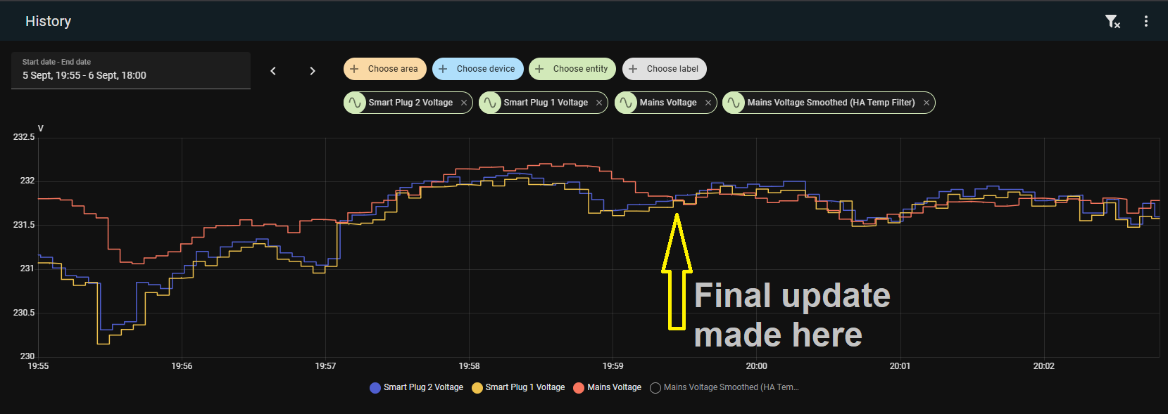
Just in case anyone was following this post, I have an updated version of the custom_sensor.h file, as I noticed (Only after hacking the 2 x Tuya ![]() smart plugs I bought over 3 years ago) that the mains voltage on the ZMPT101 was drifting due to heat and cold (3v higher than what was measured with an actual meter around 2PM, and 3v lower at 2AM according to dashboard stats (I’m not one of those people that run around the house at 2AM metering stuff for fun).).
smart plugs I bought over 3 years ago) that the mains voltage on the ZMPT101 was drifting due to heat and cold (3v higher than what was measured with an actual meter around 2PM, and 3v lower at 2AM according to dashboard stats (I’m not one of those people that run around the house at 2AM metering stuff for fun).).
It wasn’t really something that would normally bug me, but now having 2 perfectly set up smart plugs that showed the discrepancy between smart plug and ZMPT101, and being that it was a bit of an eyesore on the dashboard, decided the code had to be changed somewhat to eliminate the drift.
#include "esphome.h"
#include <Arduino.h>

#define VMAX 250
#define FREQUENCY 50
#define CALIBRATE_READ 130
#define CALIBRATE_ACTUAL 228.50  // <<< Leave this alone after initial calibration!

int ZERO_VAC = 0; // will be set dynamically in setup()

class ZMPT101BSensor : public PollingComponent, public Sensor {
  public:
    float Vrms_filtered = 0; // smoothed voltage
    const float Vrms_min = 210.0; // minimum plausible mains voltage

    // <-- Set this to the actual voltage measured when the ZMPT was first installed
    const float REFERENCE_VOLTAGE_AT_SETUP = 228.92; // <<< Change this to align with actual voltage.

    float SCALE = 1.0; // scaling factor, computed at startup

    ZMPT101BSensor() : PollingComponent(1000) {} // 1 second update
    float get_setup_priority() const override { return esphome::setup_priority::HARDWARE; }

    void setup() override {
      // Dynamically calculate ZERO_VAC at startup
      long sum = 0;
      const int samples = 500;
      for (int i = 0; i < samples; i++) {
        sum += analogRead(A0);
        delayMicroseconds(50);
      }
      ZERO_VAC = sum / samples;

      // Take a quick measurement to determine the initial scaling
      const int cycles = 5;
      float Vrms_sum = 0;
      for (int c = 0; c < cycles; c++) {
        uint32_t period = 1000000 / FREQUENCY;
        uint32_t t_start = micros();
        uint32_t Vsum = 0, measurements_count = 0;
        int32_t Vnow;
        while (micros() - t_start < period) {
          Vnow = analogRead(A0) - ZERO_VAC;
          Vsum += Vnow * Vnow;
          measurements_count++;
        }
        Vrms_sum += sqrt(Vsum / measurements_count);
      }
      float Vrms_avg = Vrms_sum / cycles;
      float Vrms = Vrms_avg / CALIBRATE_READ * CALIBRATE_ACTUAL;

      // Compute the scaling factor so the sensor reading matches the reference voltage
      SCALE = REFERENCE_VOLTAGE_AT_SETUP / Vrms;

      Vrms_filtered = Vrms * SCALE; // initialize filtered value
    }

    void update() override {
      const int cycles = 5; // number of AC cycles to average
      float Vrms_sum = 0;

      for (int c = 0; c < cycles; c++) {
        uint32_t period = 1000000 / FREQUENCY;
        uint32_t t_start = micros();
        uint32_t Vsum = 0, measurements_count = 0;
        int32_t Vnow;

        while (micros() - t_start < period) {
          Vnow = analogRead(A0) - ZERO_VAC;
          Vsum += Vnow * Vnow;
          measurements_count++;
        }

        Vrms_sum += sqrt(Vsum / measurements_count);
      }

      float Vrms_avg = Vrms_sum / cycles;
      float Vrms = Vrms_avg / CALIBRATE_READ * CALIBRATE_ACTUAL;

      // apply the scaling factor so it matches the reference voltage at setup
      Vrms *= SCALE;

      // apply a small smoothing to prevent jitter
      const float alpha = 0.1; // 0.05–0.2 for more/less smoothing
      if (Vrms_filtered == 0) {
        Vrms_filtered = Vrms; // first update
      } else {
        Vrms_filtered = alpha * Vrms + (1 - alpha) * Vrms_filtered;
      }

      // clamp to minimum plausible voltage to stop slow downward drift
      if (Vrms_filtered < Vrms_min) Vrms_filtered = Vrms_min;

      publish_state(Vrms_filtered);
    }
};
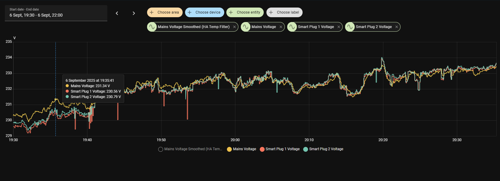
So, hopefully this might be a better solution if you are looking for something a little more “precise”, or alternatively, because you are getting annoyed at looking at the drift.
Ps. I take no credit for this, just give chatgpt a round of aplause if you must

Ps. Update: Still getting around 1v drift higher during the day, but at least it isn’t 3v+/-, however, at this point I think I am just splitting hairs (",)/
Hi
Thanks for your involvement in this thread.
I’m starting myself to run zmpt102b and esp32 together with home assistant, but drift is making me ill…
Could you advice beginner how to use your code in order to test if it will work in my setup?
Kind regards,
Marcin
Hi.
After a couple of days of messing around, I just resorted to using the following custom_sensor.h code:
#include "esphome.h"
#include <Arduino.h>

#define FREQUENCY 50
#define CALIBRATE_READ 130

class ZMPT101BSensor : public PollingComponent, public Sensor {
  public:
    static ZMPT101BSensor *instance;   // global pointer

    ZMPT101BSensor(float reference_voltage) : PollingComponent(1000) {
      this->reference_voltage = reference_voltage;
      instance = this;  // store pointer to the one and only instance
    }

    void set_scale(float new_scale) {
      this->scale = new_scale;
    }

    float get_setup_priority() const override { return esphome::setup_priority::HARDWARE; }

    void setup() override {
      // Restore last voltage reading if available
      this->pref_ = global_preferences->make_preference<float>(this->get_object_id_hash());
      float restored_value;
      if (this->pref_.load(&restored_value)) {
        this->publish_state(restored_value);
        ESP_LOGD("ZMPT101B", "Restored voltage: %.2f V", restored_value);
      }

      long sum = 0;
      const int samples = 500;
      for (int i = 0; i < samples; i++) {
        sum += analogRead(A0);
        delayMicroseconds(50);
      }
      zero_vac = sum / samples;

      // Initial scale (fallback default)
      scale = reference_voltage / CALIBRATE_READ;

      // Schedule a delayed call to apply saved calibration after ESPHome fully starts
      this->set_timeout(1000, [this]() {
        if (id(zmtp_calibration).has_state()) {
          this->set_scale(id(zmtp_calibration).state);
          ESP_LOGD("ZMPT101B", "Applied restored calibration: %.3f", id(zmtp_calibration).state);
        }
      });
    }

    void update() override {
      const int cycles = 5;
      float Vrms_sum = 0;

      for (int c = 0; c < cycles; c++) {
        uint32_t period = 1000000 / FREQUENCY;
        uint32_t t_start = micros();
        uint32_t Vsum = 0, measurements_count = 0;
        int32_t Vnow;

        while (micros() - t_start < period) {
          Vnow = analogRead(A0) - zero_vac;
          Vsum += Vnow * Vnow;
          measurements_count++;
        }

        Vrms_sum += sqrt(Vsum / measurements_count);
      }

      float Vrms_avg = Vrms_sum / cycles;
      float Vrms = Vrms_avg * scale;

      // Only save and publish if the reading seems valid (between 180V and 260V)
      if (Vrms >= 210.0 && Vrms <= 250.0) {
        this->pref_.save(&Vrms);
        publish_state(Vrms);
      } else {
        // For invalid readings, just publish without saving
        publish_state(Vrms);
        ESP_LOGW("ZMPT101B", "Invalid voltage reading: %.2f V - not saving to flash", Vrms);
      }
    }

  private:
    float reference_voltage;
    float scale = 1.0;
    int zero_vac;
    ESPPreferenceObject pref_;  // For storing last voltage reading
};

// Define the static member variable outside the class
ZMPT101BSensor *ZMPT101BSensor::instance = nullptr;
With the nodes code being updated to (relevant parts only):
esphome:
  name: "mains-voltage"

  includes:
    - custom_sensor.h
    # - zmpt101b_custom_sensor.h

  on_boot:
    priority: -100
    then:
      - delay: 2s
      - if:
          condition:
            lambda: 'return id(zmtp_calibration).has_state();'
          then:
            - lambda: |-
                ESP_LOGD("main", "Restoring calibration: %.3f", id(zmtp_calibration).state);
                if (ZMPT101BSensor::instance) {
                  ZMPT101BSensor::instance->set_scale(id(zmtp_calibration).state);
                  ESP_LOGD("main", "Calibration restored successfully");
                }
          else:
            - lambda: 'ESP_LOGW("main", "No calibration value to restore");'

external_components:
  - source:
      type: git
      url: https://github.com/robertklep/esphome-custom-component
    components: [ custom, custom_component ]

substitutions:
  sen_id: mains_voltage
  sen_name: Mains Voltage
  zmtp_voltage_ref: "231.5"

sensor:
# Mains Voltage Sensor
  - platform: custom
    lambda: |-
      static auto my_sensor = new ZMPT101BSensor(${zmtp_voltage_ref});
      App.register_component(my_sensor);
      return {my_sensor};

    sensors:
      id: ${sen_id}
      name: "${sen_name}"
      unit_of_measurement: "V"
      device_class: voltage
      state_class: "measurement"
      accuracy_decimals: 2

binary_sensor:
  - platform: template
    id: mains_status
    name: "Mains Status"
    lambda: |-
      return (!isnan(id(${sen_id}).state) && id(${sen_id}).state > 140.0);

number:
  # Input Number for adjusting values on the fly
  - platform: template
    name: "ZMPT Calibration"
    id: zmtp_calibration
    min_value: 0.5
    max_value: 2.0
    step: 0.001
    restore_value: true
    initial_value: 1.0
    optimistic: true
    internal: false
    on_value:
      then:
        - lambda: |-
            // round to 3 decimals before sending to the sensor
            float rounded = roundf(x * 1000.0) / 1000.0;
            if (ZMPT101BSensor::instance) {
              ZMPT101BSensor::instance->set_scale(rounded);
            }
            // DO NOT call publish_state() here to avoid recursion!

  - platform: template
    name: "ZMPT Actual Voltage"
    id: zmtp_actual_voltage
    min_value: 180
    max_value: 260
    initial_value: 230.0
    step: 0.01
    optimistic: true
    mode: box

button:
  - platform: template
    name: "ZMPT Calibrate"
    on_press:
      then:
        - lambda: |-
            if (ZMPT101BSensor::instance && id(mains_voltage).has_state()) {
              float measured = id(mains_voltage).state;
              float actual = id(zmtp_actual_voltage).state;
              float current_scale = id(zmtp_calibration).state;
              float new_scale = (measured > 0) ? (current_scale * actual / measured) : current_scale;
              auto call = id(zmtp_calibration).make_call();
              call.set_value(new_scale);
              call.perform();
              ZMPT101BSensor::instance->set_scale(new_scale);
            }
I will now have to see if this has actually worked or not as I only implemented it today.
Apparently the drift I am seeing, is the direct result of the cheap transformer being used in the module, and my drift (currently +/-2V) occurs at around 2pm and 2am.
According to sources, the only way to mitigate this, is to place a temp probe against the transformer and then adjust values dynamically according to the temperature reported by the probe, which, in my mind just seems silly, because I never expected a lab grade component to start with, just something that measures the mains voltage “relatively” well, which is what I currently have.
So, with that said, I think mine is now good enough for what it is, and I can now adjust the offset via the ESPHome Devices page without having to re-compile every time, which was one of my main gripes.
Hope this all helps, although, as I mentioned, mine is also now back to the testing phase to see if it performs better.
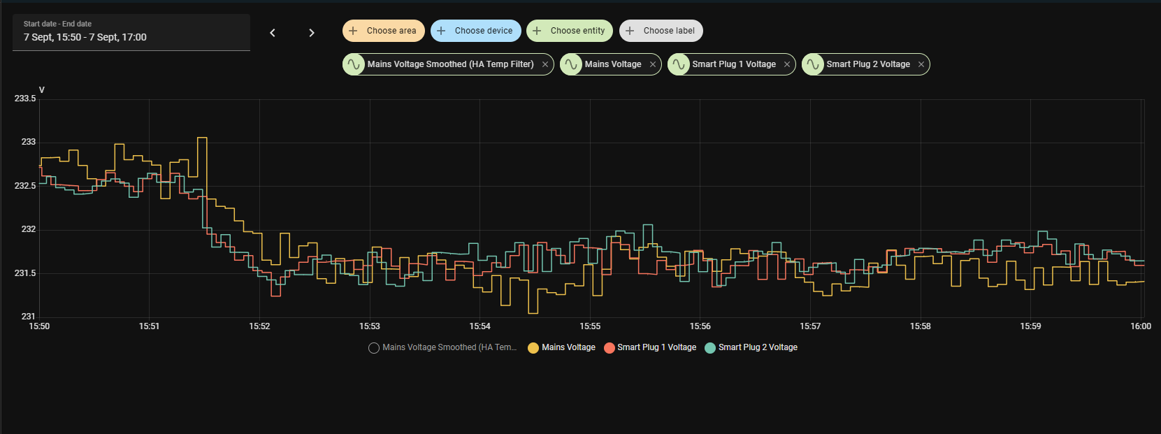
Update: Decided to re-check with the fluke and it is spot on 232.1v currently, and actually the smart plugs currently drifting by 0.5v, not the ZMPT, so the new code seems to correct the original drift I was experiencing.
Hope you come right ![]()
1 Like