These measurements are with the multimeter. impossible to connect the wrong wires.
![]()
Then you have garbage sensors. Try the one listed in the op. FSRs should not vary that much under a constant load.
Probably the shipping to my country will be more expensive than the sensor itself.
I just bought some more resistors and I’m going to test putting one of 820k or 660k. If that doesn’t work I’ll test the sensor you suggested.
Edit

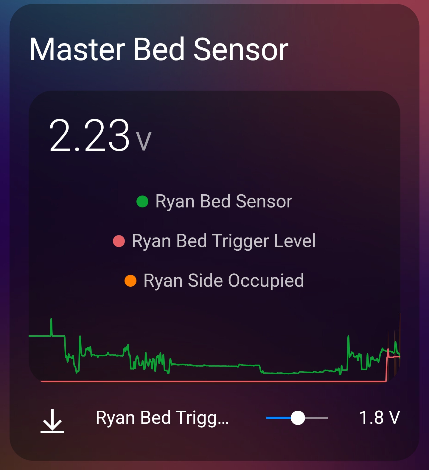
I moved in bed so there are spikes in the reading.
I think it will work with this
I can help calculating the resistor circuit.
But I need to know exactly what you connect to and what resistor circuit is already on the board. There are many postings here with different interfaces.
Your variation is not surprising. If your mattres distrubutes the load over a large area the variation will be less. It takes some experiments to get right. I use 4 load cells and found that best placement was where our butts are in bed. I placed two at the sleeping butt position and 2 at the sitting up position. They are not far from each other.
Let me know what the schematic is of the input to the a/d and which processor and we can quickly calculate component values for you
This is my setup:
R1 270 k
R3 820 k


I slightly changed the sensor to remove the empty bed readings and reverse the readings
(After doing more tests, I will invert R1 with R2.):

globals:
  - id: in_min
    type: float
    restore_value: no
    initial_value: '400'

  - id: in_max
    type: float
    restore_value: no
    initial_value: '1700'

  - id: out_min
    type: float
    restore_value: no
    initial_value: '100.0'

  - id: out_max
    type: float
    restore_value: no
    initial_value: '0.00'


sensor:
  - platform: adc
    pin: GPIO34
    attenuation: 11db
    name: "Master Bed Sensor3"
    id: "master_bed_sensor3"
    unit_of_measurement: "%"
    internal: false
    icon: mdi:bed
    update_interval: 0.5s
    raw: true
    filters:
      - lambda: |-
         if (x > id(in_max)) {
          return 0;
          } else if (x < id(in_min)) {
          return 100;
          } else {
          return ((x) - id(in_min)) * (id(out_max) - id(out_min)) / (id(in_max) - id(in_min)) + id(out_min);
          }
      - sliding_window_moving_average:
          window_size: 10
          send_every: 1
      - or:
          - throttle: 180s
          - delta: 1.00

  - platform: homeassistant
    name: "Trigger Level"
    id: "trigger_level"
    entity_id: input_number.master_bed_trigger_level
4 Likes
You seem to have some pretty good values already
With the R3 in parallel with R2 the resulting parallel resistance is Rp = 1/(1/R2 + 1/R3)
And the voltage on the A/D is then Vcc / ( 1 + R1(1/R2 + 1/R3) )
So the R3 makes the voltage change slower with change of the R2.
You are using an A/D converter input so you do not need to worry about logic level trigger levels.
The most sensitivity - as in most change of voltage with weight - is when you have no R3 and an R1 with a value that lies between the max R2 when noone is in bed and min R2 when the bed is occupied.
But we also have to consider noise. And that even though the A/D input is high impedance it is probably still some megaomhs. So we do not want too large resistor values.
To avoid hum and other electric noise to be visible on the A/D readings you want the resistance level that the A/D input looks into to be lower than 1 Mohms. And better in the hundreds of kiloohms.
The resistance that the A/D input seems can be calculated by pretending that the 3.3V is ground.
So with the 3 resistors you get all 3 in parallel. Rp = 1 / ( 1/R1 + 1/R2 + 1/R3 ). Or in numbers
1 / ( 1/270000 + 1/820000 + 1/5000000 ) which is 195 kohms. That is quite OK.
And in tne simpler form with only 1 resistor and it is the 820k the parallel impedance is 704 k. That is a bit high and can pick up hum that gets stonger when a human body is present. I would personally prefer a lower level.
RF noise can be eliminated by having a small capacitor from A/D input to ground and close to the input. But to filter hum you slow down the reaction of the system. It also depends on the length of the wire from the ESP32 to the sensor. If it is short it may be OK with a 700k impedance level. Otherwise you can try a smaller resistor like 470 k. The goal is to balance having a good dynamic range between vacant and occupied and also keeping the noise sensitivity low.
Fantastic idea and design.
I finally got around to making the 2 person version that was mentioned in the comments by DS-home.
My side worked fine and out of bed, the voltage varies/ fluctuated about 0.2V.
My partner though was varying a lot, from 3.2V all the way down to about 0.5V every 30 odd seconds. Turns out the base of the bed, where I was laying the FSR, had a stiff bit of foam that I didn’t notice. I had some 3mm MDF wood sheet laying around so I sat that under the FSR on my partners side and it helped a lot. I recalculated the resister to use for R1 and it was much lower (40k ohms instead of 270k ohms).
Once I did these changes, the voltage varies by about 0.5V which is much better than before
1 Like
@tom_l
Wow this is amazing. I am making one each for my wife and I. I’m so glad I found this as my first esphome project…wonderful easy write up, amazing directions and thank you for the pictures and diagrams.
I ended up making one sensor at 120cm long I wired two together for my “side of the bed” as I’m a thrasher and take up 2/3 of the bed. The wife has two sleeping positions so I’m making hers tomorrow with one 60mm.
I have about 86k in resistors in line…(my ocd lol)…and get a range from 2.2 down to about .75 while in bed and that varies while I’m moving around. My trigger level is currently 1.2 as that not only keeps me in bed while I roll about, it doesn’t trigger with dogs and kids.
I had to use a piece of plywood to raise the sensor a bit due to the bed being a 22" memory foam mattress. I read every post and tip in this thread, again thank you so much for this.
Now to rebuild my night and morning automations as I’ve been using them with toggle actions for years.
Great writeup! I’ve built this but am at a loss as to the wildly varying readings I’m getting.
I have two FSRs, one for each side of the bed. One measures 4,200 ohms while in bed, the other 110,000 ohms. Both read 0.L while out of bed, which on my multimeter should be above 20 meg ohms.
According to the equation I have R2 = 290k and R2 = 1,400k respectively.
However, the voltage readings vary wildly between 0.5 and 2.9 volts, regardless of me being in bed or not.
I’m using an ESP32 on GPIO 34 and 35.
I have tried several different values for R2, even without any resistors.
When I unplug everything, the “blank” GPIO gives me a steady reading of 0.5v. However, as soon as I hook up anything to one pin, even the other pin starts showing erratic readings, although nothing is connected to it…
Did I screw up my board?
Sounds like you have noise comming in. Probably hum.
Can you draw a diagram and take a picture of the setup?
It all just worked, but now I want to add a second sensor.
So I started first to rename all the stuff (just added the number 1 in the names). Everything seems to work, except the graph ?

What do I miss ?
binary_sensor:
  - platform: template
    name: "Bed Left Occupancy 1"
    device_class: occupancy
    id: bed_left_1
    lambda: |-
      if (id(bed_left_sensor_1).state < id(bed_left_trigger_level_1).state) {
        return true;
      } else {
        return false;
      }

  - platform: template
    name: "Bed Right Occupancy 1"
    device_class: occupancy
    id: bed_right_1
    lambda: |-
      if (id(bed_right_sensor_1).state < id(bed_right_trigger_level_1).state) {
        return true;
      } else {
        return false;
      }

sensor:

  - platform: adc
    pin: GPIO34
    attenuation: 11db
    name: "Bed Left Sensor 1"
    id: "bed_left_sensor_1"
    icon: mdi:bed
    update_interval: 0.5s
    filters:
      - sliding_window_moving_average:
          window_size: 10
          send_every: 1
      - or:
          - throttle: 180s
          - delta: 0.02

  - platform: adc
    pin: GPIO35
    attenuation: 11db
    name: "Bed Right Sensor 1"
    id: "bed_right_sensor_1"
    icon: mdi:bed
    update_interval: 0.5s
    filters:
      - sliding_window_moving_average:
          window_size: 10
          send_every: 1
      - or:
          - throttle: 180s
          - delta: 0.02

  - platform: homeassistant
    name: "Bed Left Trigger Level 1"
    id: "bed_left_trigger_level_1"
    entity_id: input_number.number_bed_left_trigger_level_1
  - platform: homeassistant
    name: "Bed Right Trigger Level 1"
    id: "bed_right_trigger_level_1"
    entity_id: input_number.number_bed_right_trigger_level_1
  - type: entities
    entities:
      - color_thresholds_transition: hard
        entities:
          - entity: sensor.bed_occupancy_bed_left_sensor_1
            name: Bed Sensor
            color: '#0da035'
            show_fill: false
          - entity: input_number.number_bed_left_trigger_level_1
            name: Trigger Level
            color: '#e45e65'
            show_fill: false
          - color: rgb(255,128,0)
            entity: binary_sensor.bed_occupancy_bed_left_occupancy_1
            name: Occupancy
            show_line: false
            y_axis: secondary
        group: false
        hour24: true
        hours_to_show: 24
        line_width: 2
        points_per_hour: 12
        show:
          icon: false
          name: false
          extrema: false
          average: false
          fill: fade
          labels: false
          state: true
        state_map:
          - label: Out
            value: 'off'
          - label: In
            value: 'on'
        type: custom:hui-element
        card_type: custom:mini-graph-card
        card_mod:
          class: inline-card-no-border
      - entity: input_number.number_bed_left_trigger_level_1
        name: Trigger Level
    show_header_toggle: false
    state_color: true
    title: Bed Left Sensor
States seems OK :

Logs also seems OK :

What I see is that the name of the entity id’s are now preceded with the name of the ESPHome project f.e. binary_sensor.bed_left_occupancy_1 changed to binary_sensor.bed_occupancy_bed_left_occupancy_1 ?


Maybe this is a stupid newbie question but where do the lines go, the ones that connect to 5V and G, out of the picture in the lower right corner?
To a 5V DC 1A plug pack.
Oh right. I did not think about it.
Is this something mandatory? Because I can connect the D1 Mini to a power source via the built-in USB.
No not mandatory. You can power it from the USB port instead.
Great, good to know.
Anyway, I tried to follow your guide but somehow it’s not working. It stuck on 0.00 V.
What am I doing wrong?
binary_sensor:
  - platform: template
    name: "Bed Occupied"
    id: bed_occupied
    lambda: |-
      if (id(bed_pressure).state < id(trigger_level).state) {
        return true;
      } else {
        return false;
      }

sensor:
  - platform: adc
    pin: A0
    name: "Bed Pressure"
    id: bed_pressure
    update_interval: 0.5s
    filters:
      - multiply: 3.3
      - sliding_window_moving_average:
          window_size: 10
          send_every: 1
      - or:
          - throttle: 180s
          - delta: 0.02

  - platform: homeassistant
    name: "Trigger Level"
    id: "trigger_level"
    entity_id: input_number.ariel_bed_trigger_level


Excuse me if my question is stupid as I am still wrapping my head around the concept.
If I gain/lose some not insignificant amount of body weight (let say 5kg/10lbs), does this mean that the numbers will get inaccurate and I will have to redo the calculations and replace the resistor? Or it won’t be that sensitive?
It might matter if you lose a lot of weight. Gaining weight should only make it even more easy to differentiate between in and out of bed measurements.
1 Like
Turns out one of the ground pins on my ESP32 is f’ed. I’m now using the other ground pin and everything works like a charm.
this is just great. my automations are much better than before now.
For the bed sensor, i tried 3 different sensors and only one fit me the best, it’s maybe because we have a huge bed and it’s not really transmitting the weight properly to the base. Here’s the link for the sensor I used: https://amzn.to/3QLs7nK