I’ve finally managed to get some time to work on connecting my AC using your project and all the tips from the discussion. I figured I could share my experience. Spoiler alert: everything works!
To start with, I basically went with all the components suggested in the original post by @rabbit-aaron, except for the buck converter which I replaced by a 360 mini. It is way more compact, but the drawback in my opinion is the adjustable output tension through a quite sensitive screw. It was not easy to get to 5v and avoid hitting the screw too much in order not to change the setting.
It was my first prototype board ever. So it took me a long time planning the components positions and connections. Also I’m not that familiar with soldering, so I patiently did it thinking twice or thrice before maiing the connections! At the end, I ended up with a compact board of the same size of the esp32, which is nice. I’m pretty sure it could be even more compact and a design with pin connectors instead of direct soldering for the esp32 would be better, nevertheless, I’m satisfied with the result. Especially because it was small enough to be inserted in the wall cavity.
On the soft side, it was rather easy, although I must thank @jirm for his tip to modify the code: it worked like a charm.
In HA a simple climate card will do the trick in the interface. It is a two-way connection between the wall-mounted remote and HA, so everything is synchronized.
I would like to thank you all for this great project and for the information shared!
i’m new here and just found this conversation. The way i see it, this is about communicating with the old 3-wire remote-controller, is that correct? Fujitsu starts to switch to 2-wire remote controllers two years ago, is there already a BUS hack for that (2-wire)?
What I’ve done here is take their work and put it together with the ESPHome API. If anyone has decoded the new 2-wire protocol, I could help with building an ESPHome layer on top of it, but I wouldn’t be able to test them as I don’t have the 2-wire AC unit.
Hey jirm, I’m not too familiar with the ESPHome API nor the FreeRTOS API, what does priority 1 here mean?
I have tried something like this before, but when WiFi is flaky and sometimes the ESP32 missed a frame or something, and my master controller will report an error, I had to power cycle it.
Thus my decision to pin the serial task to the second core with the highest priority.
I’m thinking of using two chips, one to handle the serial and another just to handle communication with ESPHome/Home assistant.
Hi @rabbit-aaron, Yes I totally agree with you which is not a good solution because task priority 1 means the Serial task will be executed at lower priority lever and can be seriosly compromissed by other EspHome core processes and on certain circumstances maybe some frames can be lost and the ESP can go out of sync (bound) at the LIN bus.
But with actual EspHome version a task priority putting a upper level to 1 causes a bootloop to the ESP, so seems EspHome core tasks are not happy at all executing any other high priority task (I tried on both cores) that tries to run in parallel to the EspHome core processes.
I can only say that several days in test my ESP device had not lossing sync, so seems the device are enough stable at the moment. So mean while we cannot find a best solution to elevate the priority for the serial task that can affort the device can boot and keeps working with actual EspHome version at least with this workaround Esp devices can be build and running at the moment.
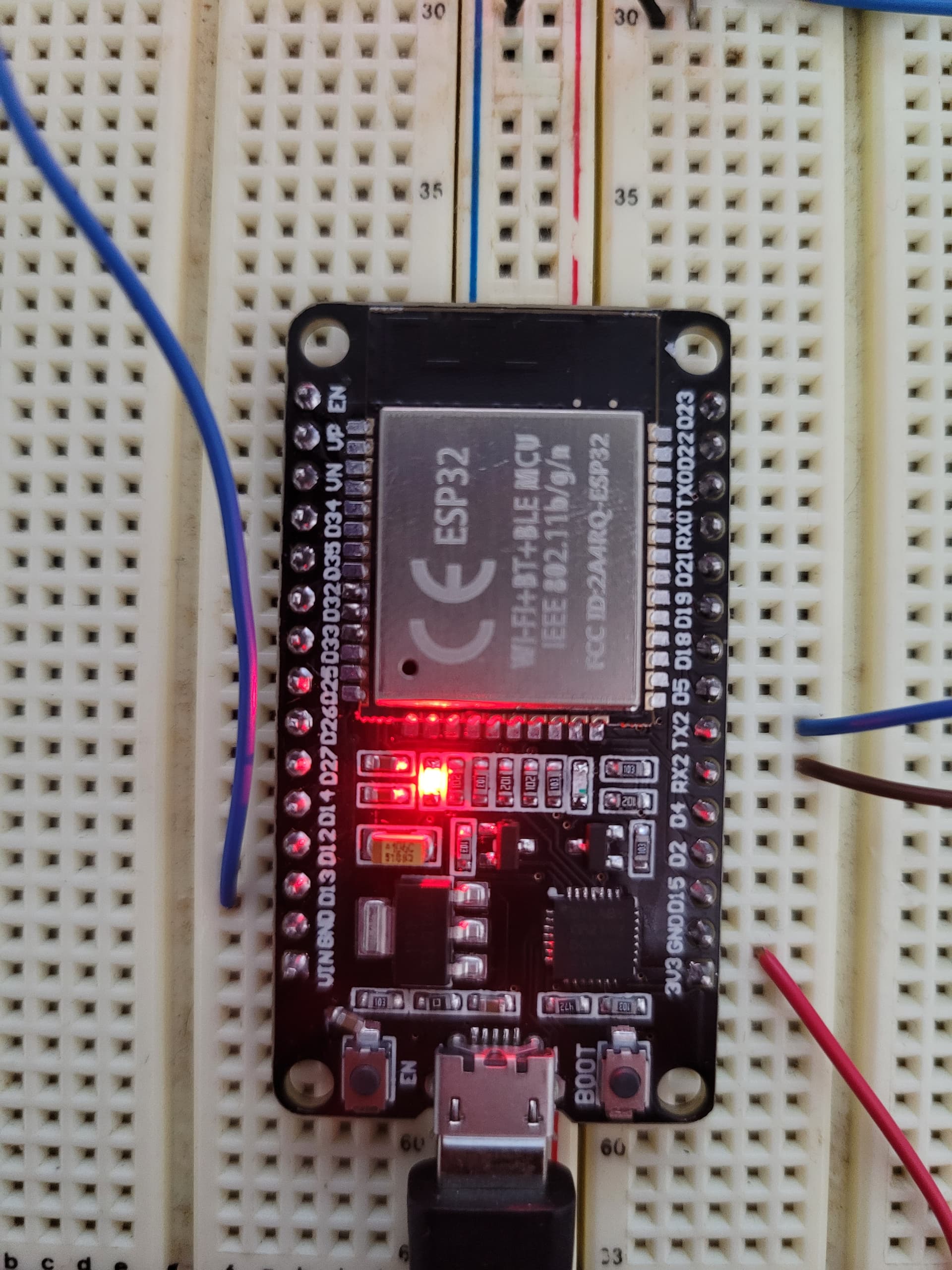
Found my loopback issue , just connect ESP32 to my fujitsu and voila everything boot well I was thinking only esp32 with program running without connect to Fujitsu will be ok for the first test on breadboard.
Order wrong LIN number but MCP2021-330E/P works well too
My Fujitsu Heatpump have Quiet mode (low low speed) for night that will be great add for the night but i’ll start with this and look around if possible to add.
Same trouble for me (looptask), did you find anything.
ELF file SHA256: 0000000000000000
Rebooting… ets Jul 29 2019 12:21:46
rst:0xc (SW_CPU_RESET),boot:0x13 (SPI_FAST_FLASH_BOOT) configsip: 0, SPIWP:0xee clk_drv:0x00,q_drv:0x00,d_drv:0x00,cs0_drv:0x00,hd_drv:0x00,wp_drv:0x00 mode:DIO, clock div:2 load:0x3fff0030,len:1184 load:0x40078000,len:13132 load:0x40080400,len:3036 entry 0x400805e4 [I][logger:258]: Log initialized [C][ota:469]: There have been 7 suspected unsuccessful boot attempts. [D][esp32.preferences:113]: Saving 1 preferences to flash… [D][esp32.preferences:142]: Saving 1 preferences to flash: 0 cached, 1 written, 0 failed [I][app:029]: Running through setup()… [D][fuji:028]: Fuji initialized [D][fuji:035]: starting task [D][fuji:010]: reached task [D][fuji:011]: serialTask started on core 1 E (10360) task_wdt: Task watchdog got triggered. The following tasks did not reset the watchdog in time: E (10360) task_wdt: - loopTask (CPU 1) E (10360) task_wdt: Tasks currently running: E (10360) task_wdt: CPU 0: IDLE E (10360) task_wdt: CPU 1: FujiTask E (10360) task_wdt: Aborting.
Eventually after about a month of this error On and Off - the error is permanent and the outdoor unit is no longer communicating with the indoor = a very hot summer without the compressor working…
Had someone come around and diagnosed, replaced the outdoor unit PCB’s, so back in operation again.
As you had mentioned, the code is set to run as a slave and not a master controller - does this esp32 controller need to be wired in a daisy chained from the main master control panel(behind)?? Or can it be wired directly from the 3 terminals at the roof indoor unit where the master controller is wired to?
In theory, I don’t see any difference in either of the wiring options mentioned above, however fujitsu documentation suggests the slave controllers to be daisy chained to the main master controller(behind)…
I have wired the esp32 directly into the roof indoor unit, and after spending 2k to fix the outdoor unit pcb - I’m trying to find the cause.
Done Fujitsu ASU12RL AOU12RL
Wall remote UTY-RNBYU
Communication box kit UTY-XCBXE (need for 12RL maybe 9RL not included for add wall remote)
Lin transceiver, wrong # order but, MCP2021-330E/P works well
Amazon esp32 dev board 30pin
LM 2596 DC-DC convertor
Project install in a small box behind the wall in entry closet.
Only missing fan mode Quiet (slow speed) in home hassistant , Quiet fan mode support by IR or wall remote ?
Lin transceiver need to but connect with AC else ESP32 will enter in bootloop
For my wall remote (UTY-RNBYU) no need to swith DIP switch1 -2 for dual controller, in dual mode error ? single mode everything works without any error ?
nicely done! looks good!
Likely those in boot loop had some wiring issue with the LIN transceiver. Note that Tx connects to Tx and Rx connects to Rx, unlike the other UART connections.
There is a fix for the Economy mode, not sure if that’s what u mean by quiet mode. I’ll update the library later to attempt to support it.
And I plan on fixing the intermittent problems where settings might not work, and you have to send the control command several times.
Quiet is only slow fan speed perfect for the night.
Economy (operation) Mode probably refer for Eco mode see the photo for description.
I never use this Economy Operation Mode I install the wall keypad for got remote temperature sensor for better temperature control and for weekly timer but the timer is so dumb i stop use it.
Hi Fosv,
thanks for the hard work you’ve put into this. I’ve actually sent the gerber files to JLPCB and got back as pictured. I guess I didn’t know the 90 degree bend in the header pins. Can I ask you how you achieve this ?
Be careful, there is an error in the schematic that I am just noticing now: TX and RX should be moved up one pin, specifically Pin 22 goes to TX and Pin 19 to RX.
So if you have already had the board manufactured, I strongly encourage you to make the correction by cutting the tracks going to the wrong Pins and to bring them via small copper wires to the right Pins. In the meantime I undertake to correct the files in the mega folder as soon as possible.
Net of this the 90° bent connectors are from Samtec, specifically models TSM-105-01-F-SV (5 Pins) and TSM-104-01-F-SV (4 Pins).
I attach the schematic of the new version that I am going to upload to Mega.
!!! Edit: Here the new version of this project with all corrections !!!
Thanks for for the information. I accidently ordered a couple wrong parts, so I’ll just get it re-manufactured. Is there any chance you would be interested releasing the CAD file under an open source license? Would be great to add to the repos with a PR
I’d like to build something with everything integrated, rather than using separate modules, but I have no PCB knowledge, is this something you might be interested in?
I’ve just had Solar installed and am going to embark on this project to intergrate our three controllers (same as @rabbit-aaron is using) into Home Assistant to give me better control.
My first stumbling block is how the heck does the face of the controller come off? I can see a couple of tabs on the bottom edge but can’t get it to release.
Yes, something with a buck converter built in, a esp32 chip with all of its supporting components, so no external esp32 dev kit, and the lin transceiver. Basically all in a small package. No external daughter boards


 I was thinking only esp32 with program running without connect to Fujitsu will be ok for the first test on breadboard.


 I never use this Economy Operation Mode I install the wall keypad for got remote temperature sensor for better temperature control and for weekly timer but the timer is so dumb i stop use it.
