Adding here for referance how I integrated a Fibaro Smart Implant to control garage door opening and status with 4 states: Open , Closed, Opening and Closing.
This is the device I used: https://manuals.fibaro.com/smart-implant/
The reason I chose this is it is super tiny and powered by 24VDC from my existing garage door opener terminal block and has relay output and 2 digital inputs for determining state.
One thing to take note of though is that when using common NO magnetic reed switches parameters 20 and 21 should be set to 'Normally closed alarm input"
When pairing the device it should be paired as not secure so that local protection state can be set to NOOperationPossible. This is necessary to de-couple the digital inputs from the relay outputs
The following code to be inserted into your configuration.yaml
template:
  - trigger:
    - platform: state
      entity_id:
        - binary_sensor.garage_door_open
        - binary_sensor.garage_door_closed
    sensor:
      - name: 'Garage Door Status'
        unique_id: 'garage_door_status'
        state: >
          {% if (trigger.to_state.state == 'off' and trigger.entity_id == 'binary_sensor.garage_door_open') %}
            Open
          {% elif (trigger.to_state.state == 'off' and trigger.entity_id == 'binary_sensor.garage_door_closed') %}
            Closed
          {% elif (trigger.to_state.state == 'on' and trigger.from_state.state == 'off' and trigger.entity_id == 'binary_sensor.garage_door_open') %}
            Closing
          {% elif (trigger.to_state.state == 'on' and trigger.from_state.state == 'off' and trigger.entity_id == 'binary_sensor.garage_door_closed') %}
            Opening
          {% endif %}
cover:
  - platform: template
    covers:
      garage_door:
        device_class: garage
        friendly_name: "Garage Door"
        unique_id: 'garage_door'
        value_template: "{{ states('sensor.garage_door_status') }}"
        icon_template: >-
          {% if states('sensor.garage_door_status') == 'Closed' %}
            mdi:garage-variant
          {% else %}
            mdi:garage-open-variant
          {% endif %}
        open_cover:
          - condition: state
            entity_id: sensor.garage_door_status
            state: "Closed"
          - action: switch.turn_on
            target:
              entity_id: switch.garage_door_button
        close_cover:
          - condition: state
            entity_id: sensor.garage_door_status
            state: "Open"
          - action: switch.turn_on
            target:
              entity_id: switch.garage_door_button
        stop_cover:
          action: switch.turn_on
          target:
            entity_id: switch.garage_door_button
Here you can see relay output 1 is connected to GND and PB(Push Button) and red to 24VDC and blue to GND . Inputs 1 and 2 are connected to the close and open position reed switches.
Hi this is exactly what I’m trying to setup but for a gate. I have added the device and changed the settings as shown. I’ve added your code which is giving me a syntax error that from what Ive read should still work, something about old and new way of coding. I’ve restarted HA but nothing has changed. How does the Template associate with the correct device ? Sorry it’s a very steep learning curve.
believe me i understand and I’m definitely no expert, i cobbled this together by searching these forums and thought I’d collate everything i did into this post. i believe the “service” call is now replaced by “action” this may resolve the syntax warning see here Services are now actions | Home Assistant Developer Docs . I’m not sure what you mean about associating with the device, and what do you mean nothing changed? have you looked under settings/“devices and services”/entities to find the new sensor and cover entities?
edit: they should appear under settings/“devices and services”/helpers also
Thanks for the reply after lots of tinkering Ive managed to get it working as required.
Beautiful! I’m gonna try this!
Can you create a little schema drawing on how you connect it exactly?, what colors go to where? thnx
straight from the manual. I only use out 1 to simulate a button press. In1 and In2 are the garage door open and close position reed switches. Power to the FGBS (P) , the relay outputs (OUT 1, OUT 2) and the 2 inputs (IN1,IN2) all share a common ground (GND).
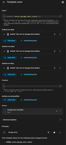
After updating to 2025.8.0 I have removed the cover: entry in my config.yaml and setup using template cover helper instead - note the trigger template entry is still required in configuration.yaml to enable opening and closing states.
so this is the only required code in configuartion.yaml :
template:
  - trigger:
      - platform: state
        entity_id:
          - binary_sensor.garage_door_open
          - binary_sensor.garage_door_closed
    sensor:
      - name: "Garage Door Status"
        unique_id: 'garage_door_status'
        state: >
          {% if (trigger.to_state.state == 'off' and trigger.entity_id == 'binary_sensor.garage_door_open') %}
            Open
          {% elif (trigger.to_state.state == 'off' and trigger.entity_id == 'binary_sensor.garage_door_closed') %}
            Closed
          {% elif (trigger.to_state.state == 'on' and trigger.from_state.state == 'off' and trigger.entity_id == 'binary_sensor.garage_door_open') %}
            Closing
          {% elif (trigger.to_state.state == 'on' and trigger.from_state.state == 'off' and trigger.entity_id == 'binary_sensor.garage_door_closed') %}
            Opening
          {% endif %}


