Getting the Lilygo T-Panel (Lite) to work

Ok, this is about the Lilygo T-Panel with a resolution of 460x460 or 480x480. Unfortunately, the documentation is already misleading at this point. I bought the T-Panel Lite, which is still advertised as having a capacitive touchscreen:

In the comments on Github, however, it was made clear that the Lite version does not have a built-in touchscreen.

There are 2 repos of the T-Panel on Github:

Unfortunately, only the first one is linked on the Lilygo website, so I initially tried to get the device to work with a completely incorrect configuration and pinmap.
Even now after numerous attempts, trial and error and minor successes, some basic things are still unclear to me, e.g. the resolution of the display, which according to the website is 460x460 for the T-Panel Lite, but in the code examples on Github the display is initialized with 480x480 - so you just don’t know what is actually correct.

I would therefore like to show my current intermediate status in the hope that someone can contribute something to get the T-Panel (Lite) up and running. Let’s start with what already works:

  • The ESP32s3 can be flashed and connected with ESPHome
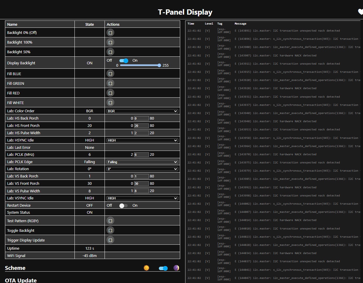
  • WiFi signal and internal temperature can be read out and displayed in HomeAssistant
  • The display backlight can be activated and changed between 0% and 100% via a slider in HomeAssistant
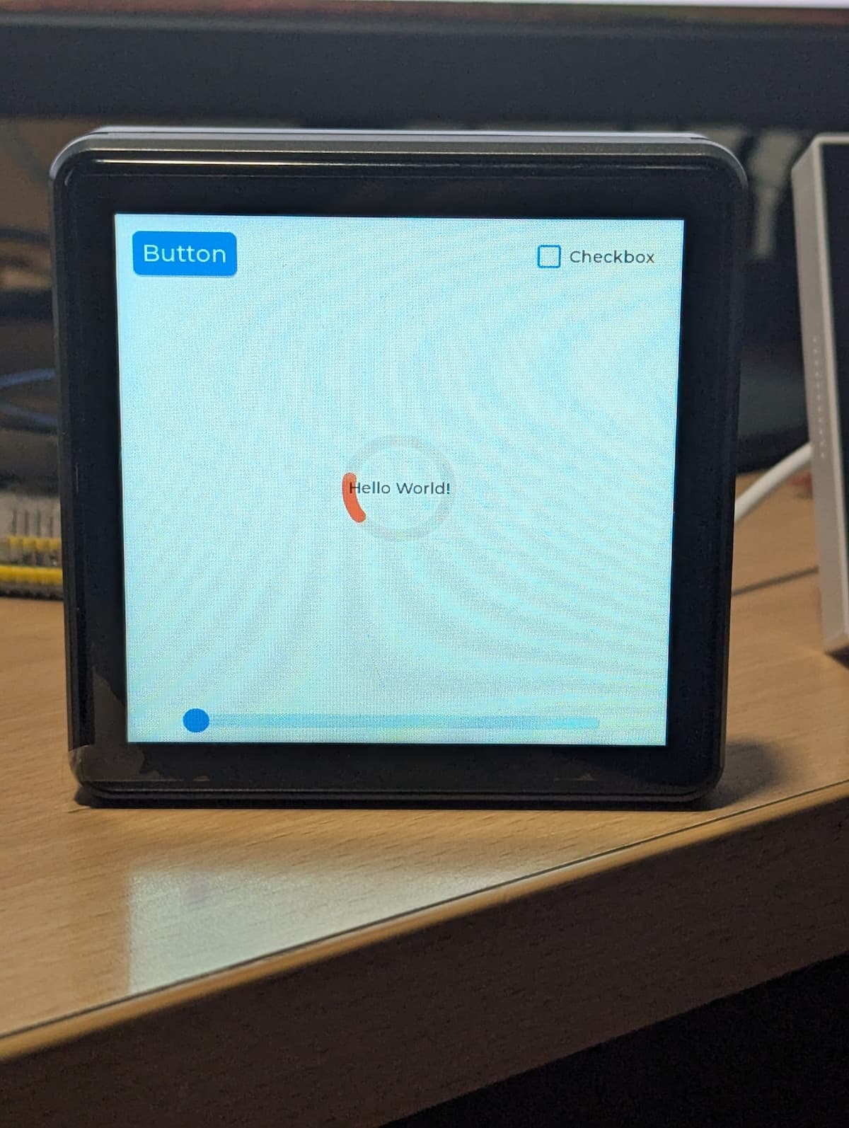
  • When the display is on, it shows colored pixels that appear and disappear in pulses

And this is my current code:

esphome:
  name: lilygo-panel
  friendly_name: Lilygo Panel
  platformio_options:
    #set frequency to 80MHz
    board_build.f_flash: 80000000L
    board_build.flash_mode: qio
    board_build.flash_size: 16MB
    #board_build.arduino.memory_type: qio_qspi
            
esp32:
  board: esp32-s3-devkitc-1
  variant: esp32s3
  flash_size: 16MB
  framework:
    type: esp-idf
    advanced:
      ignore_efuse_mac_crc: True
    #sdkconfig_options:
      #CONFIG_ESP32S3_DEFAULT_CPU_FREQ_240: y
      #CONFIG_ESP32S3_DATA_CACHE_64KB: y
      #CONFIG_SPIRAM_FETCH_INSTRUCTIONS: y
      #CONFIG_SPIRAM_RODATA: y
    sdkconfig_options:
      CONFIG_ESP32S3_SPIRAM_SUPPORT: y
      CONFIG_SPIRAM_CACHE_WORKAROUND: y
      CONFIG_ESP32S3_SPIRAM_USE: y
      CONFIG_ESP32S3_SPIRAM_SPEED_80M: y
      CONFIG_SPIRAM_BANKSWITCH_ENABLE: y
      #CONFIG_ESPTOOLPY_FLASHSIZE_16MB: y
      CONFIG_ESP32S3_DEFAULT_CPU_FREQ_240: y

logger:
  #level: DEBUG


# Enable Home Assistant API
api:
  encryption:
    key: "xxxxxxxxxxxxxxxxxxxxxxxxxxxx"

ota:
  - platform: esphome
    password: "xxxxxxxxxxxxxxxxxxxxxxxxxxxx"

wifi:
  ssid: !secret wifi_ssid
  password: !secret wifi_password

  # Enable fallback hotspot (captive portal) in case wifi connection fails
  ap:
    ssid: "Lilygo-Panel Fallback Hotspot"
    password: "xxxxxxxxxxxxxxxxxxxxxxxxxxxx"

captive_portal:
    
sensor:
  - platform: wifi_signal
    name: WLAN Signal
    update_interval: 300s
  - platform: internal_temperature
    name: Interne Temperatur
    update_interval: 300s

#psram:
  #mode: octal
  #speed: 40MHz

output:
  - platform: ledc
    pin: 
      number: GPIO33
    id: ledc_gpio
#    frequency: 100Hz

light:
  - platform: monochromatic
    output: ledc_gpio
    name: "Display Helligkeit"
    id: display_backlight
    restore_mode: ALWAYS_ON
    entity_category: config

#Display
spi:
  - clk_pin: 36
    mosi_pin: 35

display:
  - platform: st7701s
    id: disp
    #auto_clear_enabled: false
    #update_interval: never
    #spi_mode: MODE3
    #color_order: BGR
    color_order: RGB
    dimensions:
      width: 480
      height: 480
    #invert_colors: true
    #transform:
    #  mirror_x: true
    #  mirror_y: true
    cs_pin: 14
    #reset_pin: 39
    de_pin: 38
    hsync_pin: 39
    vsync_pin: 40
    pclk_pin: 41
    hsync_pulse_width: 1
    hsync_front_porch: 20
    hsync_back_porch: 1
    vsync_pulse_width: 1
    vsync_front_porch: 30
    vsync_back_porch: 10
    #pclk_frequency:
    #pclk_inverted: False
    #init_sequence:
    #  - 1 # select canned init sequence number 1
    #  - [ 0xE0, 0x1F ]  # Set sunlight readable enhancement
    setup_priority: -100
    #init_sequence:
    #  - [0xFF, 0x77, 0x01, 0x00, 0x00, 0x13]
    #  - [0xEF, 0x08]
    #  - [0xFF, 0x77, 0x01, 0x00, 0x00, 0x10]
    #  - [0xC0, 0x3B, 0x00]
    #  - [0xC1, 0x0B, 0x02]
    #  - [0xC2, 0x07, 0x02]
    #  - [0xCC, 0x10]
    #  - [0xCD, 0x08]
    #  - [0xB0, 0x02, 0x13, 0x1B, 0x0D, 0x10, 0x05, 0x08, 0x07, 0x07, 0x24, 0x04, 0x11, 0x0E, 0x2C, 0x33, 0x1D]
    #  - [0xB1, 0x05, 0x13, 0x1B, 0x0D, 0x11, 0x05, 0x08, 0x07, 0x07, 0x24, 0x04, 0x11, 0x0E, 0x2C, 0x33, 0x1D]
    #  - [0xE0, 0x00, 0x00, 0x02]
    #  - [0x11]
    #  - delay 120ms
    #  - [0x3A, 0x55]
    #  - [0x36, 0x08]
    #  - [0x29]
    #  - delay 120ms
    init_sequence:
      - [0xFF, 0x77, 0x01, 0x00, 0x00, 0x13]  # INIT 1
      - [0xEF, 0x08]                           # INIT 2
      - [0xFF, 0x77, 0x01, 0x00, 0x00, 0x10]  # INIT 3
      - [0xC0, 0x3B, 0x00]                     # INIT 4
      - [0xC1, 0x0B, 0x02]                     # INIT 5
      - [0xC2, 0x30, 0x02, 0x37]               # INIT 6
      - [0xCC, 0x10]                           # INIT 7
      - [0xB0, 0x00, 0x0F, 0x16, 0x0E, 0x11, 0x07, 0x09, 0x09, 0x08, 0x23, 0x05, 0x11, 0x0F, 0x28, 0x2D, 0x18]  # Gamma Control Positive
      - [0xB1, 0x00, 0x0F, 0x16, 0x0E, 0x11, 0x07, 0x09, 0x08, 0x09, 0x23, 0x05, 0x11, 0x0F, 0x28, 0x2D, 0x18]  # Gamma Control Negative
      - [0xFF, 0x77, 0x01, 0x00, 0x00, 0x11]  # INIT 8
      - [0xB0, 0x4D]                           # INIT 9
      - [0xB1, 0x33]                           # INIT 10
      - [0xB2, 0x87]                           # INIT 11
      - [0xB5, 0x4B]                           # INIT 12
      - [0xB7, 0x8C]                           # INIT 13
      - [0xB8, 0x20]                           # INIT 14
      - [0xC1, 0x78]                           # INIT 15
      - [0xC2, 0x78]                           # INIT 16
      - [0xD0, 0x88]                           # INIT 17
      - [0xE0, 0x00, 0x00, 0x02]               # INIT 18
      - [0xE1, 0x02, 0xF0, 0x00, 0x00, 0x03, 0xF0, 0x00, 0x00, 0x00, 0x44, 0x44]  # INIT 19
      - [0xE2, 0x10, 0x10, 0x40, 0x40, 0xF2, 0xF0, 0x00, 0x00, 0xF2, 0xF0, 0x00, 0x00]  # INIT 20
      - [0xE3, 0x00, 0x00, 0x11, 0x11]        # INIT 21
      - [0xE4, 0x44, 0x44]                     # INIT 22
      - [0xE5, 0x07, 0xEF, 0xF0, 0xF0, 0x09, 0xF1, 0xF0, 0xF0, 0x03, 0xF3, 0xF0, 0xF0, 0x05, 0xED, 0xF0, 0xF0]  # INIT 23
      - [0xE6, 0x00, 0x00, 0x11, 0x11]        # INIT 24
      - [0xE7, 0x44, 0x44]                     # INIT 25
      - [0xE8, 0x08, 0xF0, 0xF0, 0xF0, 0x0A, 0xF2, 0xF0, 0xF0, 0x04, 0xF4, 0xF0, 0xF0, 0x06, 0xEE, 0xF0, 0xF0]  # INIT 26
      - [0xEB, 0x00, 0x00, 0xE4, 0xE4, 0x44, 0x88, 0x40]  # INIT 27
      - [0xEC, 0x78, 0x00]                     # INIT 28
      - [0xED, 0x20, 0xF9, 0x87, 0x76, 0x65, 0x54, 0x4F, 0xFF, 0xFF, 0xF4, 0x45, 0x56, 0x67, 0x78, 0x9F, 0x02]  # INIT 29
      - [0xEF, 0x10, 0x0D, 0x04, 0x08, 0x3F, 0x1F]  # INIT 30
      - [0x3A, 0x55]                           # Color Mode
      - [0x36, 0x08]                           # Memory Data Access Control
      - [0x11]                                 # Sleep Out
      - [0x29]                                 # Display On

    data_pins:
      blue:
        - 1         #b0
        - 2         #b1
        - 3         #b2
        - 4         #b3
        - 5         #b4
      green:
        - 6         #g0
        - 7         #g1
        - 8         #g2
        - 9         #g3
        - 10        #g4
        - 11        #g5
      red:
        - 12        #r0
        - 13        #r1
        - 42        #r2
        - 46        #r3
        - 45        #r4
    lambda: |-
      it.print(10, 10, id(normal), "Display Test");
     
font:
  - file: "fonts/MollenBold.otf"
    id: normal
    size: 24
    bpp: 4

As you can see, I’ve already tried a lot back and forth. This is probably why the code now contains some useless or incorrect lines of code.
Hoping that at least the pin assignments are correct, I suspect the main reason for the non-functioning display is its initialization sequence. However, I cannot rule out the possibility that something else is wrong, as the Lilygo documentation cannot be relied upon.

Maybe someone has another tip for me to get the display working.

That is typical of lilygo.

Hi @nickrout , I just got the T-Panel S3 RS-485, 480x480 and stumbled upon this trying to figure out what I could do…
Did you had any progress or luck so far?

I’ve been able to upload a test with Squareline studio, not esphome trials so far.

Thanks

I found this project for Arduino and it works well on T-Panel S3 (480x480 with RS485) not the Lite version, pins are different but sharing same MCU, same display driver and RGB panel:
https://github.com/jbanyer/squareline_lilygo_t_panel_starter.

So, the init sequence is the same as yours and it works fine on arduino.

Main difference from T-Panel Lite is the presence of I/O expander which gives access to SPI pins and LCD CS and LCD Reset.
I tried my configuration, no luck.

################################
# LILYGO T-PANEL S3 [with RS485], MCU: ESP32S3
#
# resources:
# official github: https://github.com/Xinyuan-LilyGO/T-Panel 
#
# A sample project TESTED with arduino: https://github.com/jbanyer/squareline_lilygo_t_panel_starter
#   pins: https://github.com/jbanyer/squareline_lilygo_t_panel_starter/blob/1d894c426c94dd30d8f70172eb76166fae314380/lib/config/pin_config.h#:~:text=pin_config.h
#   init sequence: https://github.com/jbanyer/squareline_lilygo_t_panel_starter/blob/1d894c426c94dd30d8f70172eb76166fae314380/lib/Arduino_GFX-1.4.6/src/display/Arduino_RGB_Display.h
#
# Some pins are connected to I/O espander: SPI CLK, SPI MOSI, LCD CS, LCD RESET
# see circuit https://github.com/Xinyuan-LilyGO/T-Panel/blob/6a1f2636dc2490d0c33338926ba862c3846202fd/project/T-Panel_V1.2.pdf

substitutions:
  device_name: "tpanel_studio"
  friendly_name: "Studio T-Panel"

esphome:
  name: tpanel_studio
  friendly_name: "$friendly_name"
  comment: "Lilygo T-Panel S3"
  project:
    name: "umbex.$device_name"
    version: "v0.12"  

esp32:
  board: esp32-s3-devkitc-1
  variant: esp32s3
  flash_size: 16MB
  framework:
    type: esp-idf
    sdkconfig_options:    # not sure these are necessary 
      CONFIG_ESP32S3_DEFAULT_CPU_FREQ_240: "y"
      CONFIG_ESP32S3_DATA_CACHE_64KB: "y"
      CONFIG_ESP32S3_DATA_CACHE_LINE_64B: "y"
      CONFIG_SPIRAM_FETCH_INSTRUCTIONS: y
      CONFIG_SPIRAM_RODATA: y

psram:  # not sure these are necessary 
  mode: octal
  speed: 80MHz

logger:
  level: VERBOSE 

api:
  encryption:
    key: !secret api_password

ota:
  - platform: esphome
    password: !secret ota_password

wifi:
  ssid: !secret wifi_ssid
  password: !secret wifi_password
  id: wifi_id

  ap:
    ssid: "esphome $device_name"
    password: !secret wifi_password

captive_portal:

# serial interface 
i2c:
  sda: GPIO17
  scl: GPIO18 

# some pins are connected to I/O espander, 
# see circuit https://github.com/Xinyuan-LilyGO/T-Panel/blob/6a1f2636dc2490d0c33338926ba862c3846202fd/project/T-Panel_V1.2.pdf
xl9535:
  - id: xl9535_hub
    address: 0x20

# SPI via I2C I/O expander
spi:
  clk_pin: 
    xl9535: xl9535_hub
    number: 15  
  mosi_pin: 
    xl9535: xl9535_hub
    number: 16

display:
  - platform: st7701s
    setup_priority: -100        # SPI load error if omitted
    id: disp
    auto_clear_enabled: false    # not sure
    update_interval: 60s        # or never
    spi_mode: MODE3             # not really sure but MODE0, MODE1, MODE2 does not work either
    color_order: RGB
    dimensions:
      width: 480
      height: 480
    invert_colors: false        # not sure 
    transform:
      mirror_x: true
      mirror_y: true
    cs_pin:                     # LCD_CS pin via I/O espander 
      xl9535: xl9535_hub
      number: 17
    de_pin: GPIO0               # DE pin not exists in circuit. so... NOT USED BY THIS DISPLAY? Assigning a free pin because required
    reset_pin:                 
      xl9535: xl9535_hub      
      number: 5
    # data_rate: 8MHz           # tested, no difference 
    pclk_frequency: 6MHz        
    pclk_inverted: true         # this seems to be inverted in jbanyer's source, with "10 /* pclk_active_neg"
    hsync_pin: GPIO39           # as in jbanyer's arduino test
    vsync_pin: GPIO40           # as in jbanyer's arduino test
    pclk_pin: GPIO41            # as in jbanyer's arduino test
    hsync_pulse_width: 2        # as in jbanyer's arduino test
    hsync_front_porch: 20       # as in jbanyer's arduino test
    hsync_back_porch: 0         # as in jbanyer's arduino test
    vsync_pulse_width: 8        # as in jbanyer's arduino test
    vsync_front_porch: 30       # as in jbanyer's arduino test
    vsync_back_porch: 1         # as in jbanyer's arduino test

    init_sequence:              # as in jbanyer's arduino test
      - [0x01] # Software Reset
      - delay 120ms
      - [0xFF, 0x77, 0x01, 0x00, 0x00, 0x13]  # INIT 1
      - [0xEF, 0x08]                           # INIT 2
      - [0xFF, 0x77, 0x01, 0x00, 0x00, 0x10]  # INIT 3
      - [0xC0, 0x3B, 0x00]                     # INIT 4
      - [0xC1, 0x0B, 0x02]                     # INIT 5
      - [0xC2, 0x30, 0x02, 0x37]               # INIT 6
      - [0xCC, 0x10]                           # INIT 7
      - [0xB0, 0x00, 0x0F, 0x16, 0x0E, 0x11, 0x07, 0x09, 0x09, 0x08, 0x23, 0x05, 0x11, 0x0F, 0x28, 0x2D, 0x18]  # Gamma Control Positive
      - [0xB1, 0x00, 0x0F, 0x16, 0x0E, 0x11, 0x07, 0x09, 0x08, 0x09, 0x23, 0x05, 0x11, 0x0F, 0x28, 0x2D, 0x18]  # Gamma Control Negative
      - [0xFF, 0x77, 0x01, 0x00, 0x00, 0x11]  # INIT 8
      - [0xB0, 0x4D]                           # INIT 9
      - [0xB1, 0x33]                           # INIT 10
      - [0xB2, 0x87]                           # INIT 11
      - [0xB5, 0x4B]                           # INIT 12
      - [0xB7, 0x8C]                           # INIT 13
      - [0xB8, 0x20]                           # INIT 14
      - [0xC1, 0x78]                           # INIT 15
      - [0xC2, 0x78]                           # INIT 16
      - [0xD0, 0x88]                           # INIT 17
      - [0xE0, 0x00, 0x00, 0x02]               # INIT 18
      - [0xE1, 0x02, 0xF0, 0x00, 0x00, 0x03, 0xF0, 0x00, 0x00, 0x00, 0x44, 0x44]  # INIT 19
      - [0xE2, 0x10, 0x10, 0x40, 0x40, 0xF2, 0xF0, 0x00, 0x00, 0xF2, 0xF0, 0x00, 0x00]  # INIT 20
      - [0xE3, 0x00, 0x00, 0x11, 0x11]        # INIT 21
      - [0xE4, 0x44, 0x44]                     # INIT 22
      - [0xE5, 0x07, 0xEF, 0xF0, 0xF0, 0x09, 0xF1, 0xF0, 0xF0, 0x03, 0xF3, 0xF0, 0xF0, 0x05, 0xED, 0xF0, 0xF0]  # INIT 23
      - [0xE6, 0x00, 0x00, 0x11, 0x11]        # INIT 24
      - [0xE7, 0x44, 0x44]                     # INIT 25
      - [0xE8, 0x08, 0xF0, 0xF0, 0xF0, 0x0A, 0xF2, 0xF0, 0xF0, 0x04, 0xF4, 0xF0, 0xF0, 0x06, 0xEE, 0xF0, 0xF0]  # INIT 26
      - [0xEB, 0x00, 0x00, 0xE4, 0xE4, 0x44, 0x88, 0x40]  # INIT 27
      - [0xEC, 0x78, 0x00]                     # INIT 28
      - [0xED, 0x20, 0xF9, 0x87, 0x76, 0x65, 0x54, 0x4F, 0xFF, 0xFF, 0xF4, 0x45, 0x56, 0x67, 0x78, 0x9F, 0x02]  # INIT 29
      - [0xEF, 0x10, 0x0D, 0x04, 0x08, 0x3F, 0x1F]  # INIT 30
      - [0x3A, 0x55]                           # Color Mode
      - [0x36, 0x08]                           # Memory Data Access Control
      - [0x11]                                 # Sleep Out
      - delay 120ms
      - [0x29]                                 # Display On

    data_pins:      # as in jbanyer's arduino test
      blue:
        - 1         #b0
        - 2         #b1
        - 3         #b2
        - 4         #b3
        - 5         #b4
      green:
        - 6         #g0
        - 7         #g1
        - 8         #g2
        - 9         #g3
        - 10        #g4
        - 11        #g5
      red:
        - 12        #r0
        - 13        #r1
        - 42        #r2
        - 46        #r3
        - 45        #r4
    lambda: |-
      it.print(10, 10, id(normal), id(alert_color), TextAlign::TOP_LEFT, "Hello World!");
     
font:
  - file: "fonts/Roboto-Regular.ttf"
    id: normal
    size: 20

color:
  - id: alert_color 
    red: 100%
    green: 20%
    blue: 20%
    
sensor:
  # Uptime sensor.
  - platform: uptime
    name: "$device_name uptime"
  - platform: homeassistant
    entity_id: sensor.vmc_studio_co2
    id: vmc_studio_co2
    on_value:
      - component.update: disp    # trying to force display update

time: 
  - platform: homeassistant  # Sync time with Home Assistant.
    id: homeassistant_time
    update_interval: 30s

output:
  - platform: ledc           # Display backlight 
    pin: 
      number: GPIO14  # ok 
    id: ledc_gpio
    frequency: 100Hz
    inverted: False

light:
  - platform: monochromatic   # Display backlight 
    output: ledc_gpio
    name: "$device_name Display light"
    id: display_backlight
    restore_mode: ALWAYS_ON
    entity_category: config

another config from @clydebarrow, unfortunately not working for me either

data pins for green are typos, but there are various more syntax errors when compiling unfortunately
- GPIO10 #g4
- GPIO11 #g5

That file hasn’t been tested - it’s basically a copy of the Waveshare 4" config that I’d started to modify.

thanks for confirming.

Got this device for the idea of using it as AP for OpenEPaperLink, but then decided against it and would rather use it as display.

But as it turns out, nobody got it yet working with esphome hence I’ll probably return it. A pity, it is nice hardware and the ESP32-H2 also just got supported by esphome with the last release