Grundfos Well Controller

I am working with a Grundfos well pump that uses a CU301 controller. I am attempting to integrate it into Home Assistant with ESPHome. I would like it to have its typical functions accessible with the interface plugged in normally so all of the buttons and LEDs work if the ESP were to be offline.

Emulating the buttons is simple with a 200ms GPIO button output. However, due to the design of the circuit, the LEDs are posing a challenge. The LEDs use a common 10v DC+ line and switch the ground to illuminate. I’m wondering if anyone has an idea of how to integrate this so that a GPIO circuit can read the status of the LEDs. I have considered having the ESP board act as an LED controller, taking the inputs and controlling the LEDs separately, but this means that if the ESP stops working, I need to rewire the controller to allow for local control again.

I have attached a photo of the circuit board, if that helps. To the header, I have temporarily attached some wires for testing.

Thanks in advance!

I am also interested in this. Do you have any progress? How about using optocoupler (PC817)?

I found these articles regarding reading LED status:

It has a IR controller that runs $500+.
I am hoping to borrow one and try to scan its operation with a flipper.
It also has a INT Sensor pin on top right of board, but i haven’t figured what its for yet.

Guys, any progress on this? I have a CU 301 as well that I’d love to integrate with HA.

Any luck getting your hands on the controller (I assume you’re talking about the MI 301?)

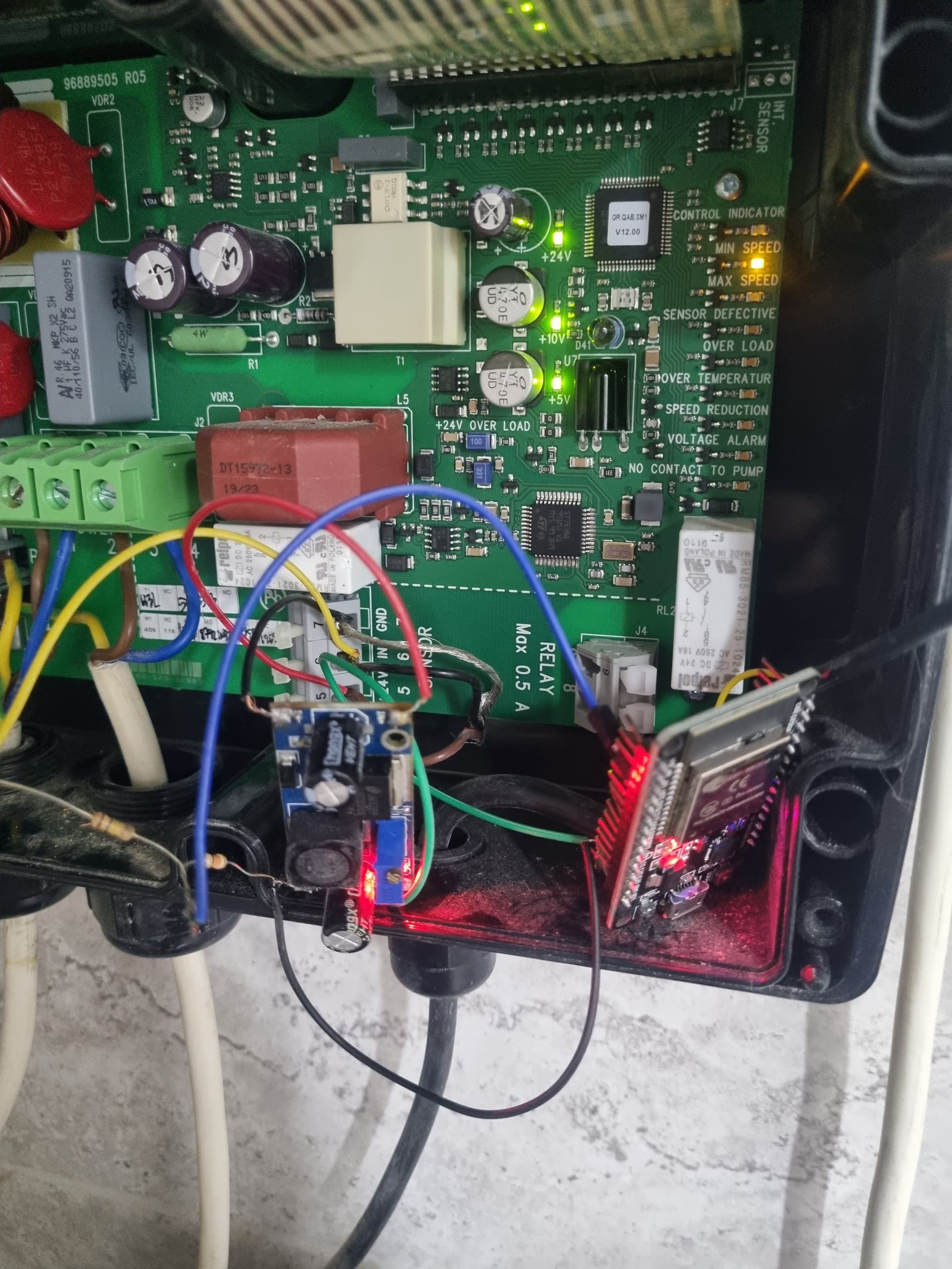
Yes, progress here! A few months ago I managed to integrate Grundfos CU 301 pump controller into Home Assistant - I will try to share my solution and experiences :wink:

KIND WARNING:
If you don’t know what you are doing, don’t do that! Your device may be damaged. There is a risk of electric injury. All you do is at your own risk!

What I wanted to achieve:

  • know the state of pump (power state, if pump is running and low water level problem)
  • be able to turn it on and off
  • make it detachable in case of any problems (without irreversible changes)
  • for safety make it electrically isolated from the pump controller

Result:
ESPHome device:


from top - on/off push button, pump is running, (extra door sensor, humidity and temperature sensor), low water level problem and on/off state

Final Lovelace card:
image
from top: on/off switch, pump is running, low water level problem

What you need:

  • ESP32 development board running ESPHome
  • at least 3 optocouplers for LED state reading
    • I used this PC817 4-channel optocoupler board (but additional modification is needed)
    • maybe easier would be 3 single optocouplers (but more boards and cables to organize inside pump controller)
  • 3.3V 1-channel relay module for on/off button pressing
  • 40 pin header socket connector for connecting cables in a detachable way
  • some (dupont) cables
  • 5V power supply (I used this one on DIN rail)

How to do that:
Here is sketch of pins inside pump controller:


from left:
“LEDs section”

  • LED plus pole (there is voltage all the time ~10.2 V)
  • maintenance LED minus pole (is connected to ground when LED is active)
  • pumping top LED minus pole
  • pumping middle LED
  • pumping bottom LED
  • low water level LED
  • 5.0 bar LED
  • 4.5 bar LED
  • 4.0 bar LED
  • 3.5 bar LED
  • 3.0 bar LED
  • 2.5 bar LED
  • 2.0 bar LED
  • turned on LED
  • turned off LED
  • locked LED

“Buttons section” - for button pres shortly connect button to GND

  • on/off button
  • pressure plus button
  • pressure minus button
  • not used
  • not used
  • GND

Note: maybe it could vary based on your HW revision…don’t know

Everything else should be clear I think :grinning:

If not, in short:
LED state detection:
Use optocouplers to parallelly connect to LEDs - be careful because all optocouplers on the board have common GND but LEDs inside the pump controller have common (+) and they are turned on by connecting to GND. You cannot interchange poles on optocouplers so either use 1-channel optocouplers or “cut” the optocouplers board (on both sides) to disconnect them. Afterthat you can interconnect IN1, IN2 and IN3 on board to reduce wiring. On output side you can interconnect GNDs to reduce wiring to ESP. Then connect GND and V1, V2 and V3 to GND and GPIO pins on ESP.

On/off button press:
At first I wanted to use also optocoupler (in reverse way) to perform button press but it had too much resistance. So that I used standard relay.

Problems:
After some time I was experiencing problems with floating states on GPIOs. I also tried different GPIOs but after some time it was the same. The solution to that was to use ADC on ESP. Now I have “pump is running” and “low water level” on ADC and “power state” on digital GPIO and it is working…today I would put all the LEDs to ADCs. Note that not all pins on ESP32 can be used as ADC, see here.

ESPHome code:

...
switch:
  - platform: gpio
    pin:
      number: GPIO19
      inverted: true
    name: "On/Off button"
    id: on_off_button
    on_turn_on:
    - delay: 500ms
    - switch.turn_off: on_off_button

binary_sensor: 
  - platform: gpio
    pin:
      number: GPIO22
      mode:
        input: true
    filters:
      - delayed_off: 100ms
      - delayed_on: 1000ms
    id: "power_gpio"
  - platform: template
    name: "Power"
    lambda: "return id(power_gpio).state;"
    filters:
      - invert

  - platform: template
    name: "Pumping"
    lambda: "return id(pumping_voltage).state < 1;"
    device_class: running
    filters:
      - delayed_off: 5000ms

  - platform: template
    name: "Low water level"
    lambda: "return id(low_water_level_voltage).state < 1;"
    device_class: problem

sensor:
  - platform: adc
    pin: GPIO32
    id: pumping_voltage
    update_interval: 500ms
    attenuation: auto

  - platform: adc
    pin: GPIO33
    id: low_water_level_voltage
    update_interval: 5s
    attenuation: auto

Home Assistant switch:

- platform: template
  switches:
    well_pump:
      unique_id: well_pump
      value_template: "{{ is_state('binary_sensor.esphome_web_d0e77c_power', 'on') }}"
      turn_on:
        service: switch.turn_on
        target:
          entity_id: switch.esphome_web_d0e77c_on_off_button
      turn_off:
        service: switch.turn_on
        target:
          entity_id: switch.esphome_web_d0e77c_on_off_button

Gallery:

Good luck and hope it helps!

2 Likes

Hi Saryn!

Actually good job!
I’m interested why didn’t you consider pressure sensor? Think this more valuable thing than other.

Alex.

I didn’t want to modify existing piping anymore (I don’t have much space there) and I also wanted to be able to turn off the pump remotely (in case of leakage or valve malfunction).

My idea was to use this connection
ced12422a9888c6f0a87cfe389012ca32a291ec1
It has pressure sensor danfoss mbs1900 on the end, I’m looking for the way how to get data from it.

Hi Gents!

So answering my question
I made some testing and discovered that pressure sensor returns the voltage depending on the actual pressure somewhere from 0 to 10v.
It has linear dependence with an offset.
ChatGPT helped me to build a formula.
But before you can use this signal with your ESP32 you have to downscale it to the range 0 to 3v (got instructions from ChatGPT as well))) using 2 resistors.
The important note is to use the same GND for esp32 and sensor, so you need to power esp32 from cu301 using LM2596S.

Instructions for yaml:

sensor:
  - platform: adc
    pin: GPIO34
    name: "Pressure Sensor Voltage"
    update_interval: 1s
    attenuation: 11db
    filters:
      - multiply: 6.69
      - lambda: |-
          return x - 0.923;
    unit_of_measurement: "bar"
    accuracy_decimals: 1

Need to calibrate a bit but in general i’m ok with it.

This scheme will work with any kind of such sensors for your automation.

Good luck.
Alexandr.

I have not had any luck finding one cheap.
I did rig up a esp with an IR receiver to see if I could pick anything up from the CU301, but I had no luck with that either.

Just a warning, the CU301 support both voltage-mode sensors as well as 0-20mA current mode sensors. So be careful with measuring the voltage on the sensor connection as it might not behave as you expect depending on what flavor it is.

I have the IR programming device that I picked up some years ago. I might try to reverse engineer what’s going on there… Using it, you can get information on the pump state (run hours, temperature, etc.) as well as other configuration data. I will have to add this to the list of home automation projects to explore…

What resistors did you use to connect to the pressure sensor? Can you provide a simple wiring diagram?

Thank you so much for posting this. I have the same well pump and I have wanted to be able to control it for years. I never thought to simulate button presses with the relay. I actually never opened the controller until I saw your post. I was going to buy a 230V contactor to switch the power on and off but this is much better and arguably safer.

I used a wemos d1 mini (esp8266) and mounted everything to a prototype board for a clean install. I only used one optocoupler since I am only interested in controlling power at the moment.

I also used a different method to expose the on/off switch to home assistant:

esphome:
  name: well-pump
  friendly_name: Well Pump


esp8266:
  board: esp01_1m

# Enable logging
logger:

# Enable Home Assistant API
api:
  encryption:
    key: "redacted"

ota:
  - platform: esphome
    password: "redacted"

wifi:
  ssid: !secret wifi_ssid
  password: !secret wifi_password

  # Enable fallback hotspot (captive portal) in case wifi connection fails
  ap:
    ssid: "Well-Pump Fallback Hotspot"
    password: "redacted"

captive_portal:

sensor:
  - platform: uptime
    name: Uptime Sensor
    id: time_since_boot

output:
  - platform: gpio
    pin: GPIO5
    id: "onoff"

button:
  - platform: output
    name: "Well Pump Toggle"
    id: "toggle"
    output: onoff
    duration: 
      milliseconds: 500

switch:
  - platform: template
    name: "Well Pump Power"
    id: "wellswitch"
    lambda: |-
      if (id(power_inverted).state) {
        return true;
      } else {
        return false;
      }
    turn_on_action:
      - lambda: |-
            if (id(time_since_boot).raw_state > 60) {
              id(toggle).press();
            }
    turn_off_action:
      - lambda: |-
            if (id(time_since_boot).raw_state > 60) {
              id(toggle).press();
            }

binary_sensor: 
  - platform: gpio
    pin:
      number: GPIO14
      mode:
        input: true
        pullup: true
    filters:
      - delayed_off: 100ms
      - delayed_on: 1000ms
    id: "power_gpio"
  - platform: template
    name: "Power"
    id: "power_inverted"
    lambda: "return id(power_gpio).state;"
    filters:
      - invert
    

The template switch by default does not assume state and is not optimistic when the switch is toggled from the front end. This makes the unit function like a normal on/off switch. I also needed to block the turn_on_action and turn_off_action for the first 60 seconds after boot to prevent the binary sensor or the home assistant front end from causing the relay to toggle on boot.


Thanks @lmamakos you’re absolutely correct, we need here another circuit. In my case it worked but not as expected.
So here’s the better option (for @laffen13)

. MBS1900 is a Grundfos pressure transmitter, so we can be very specific now.


1. Grundfos MBS 1900 – key electrical data

Typical versions of MBS 1900 have:

  • Supply voltage: 9–32 V DC (usually 24 V)
  • Output: 4–20 mA (2‑wire current loop)
  • Connector: DIN 43650 / Hirschmann
  • Pins:
    • Pin 1: +Supply / Current loop +
    • Pin 2: 0 V / Current loop –
    • Pin 3: PE (shield / ground, optional)

:warning: MBS1900 is not a voltage sensor – it is 4–20 mA only.


2. Do you need a transistor?

:white_check_mark: No transistor is needed if:

  • You have an analog input
  • You can measure 1–5 V (or 0–3.3 V with a different resistor)

The correct and simplest solution is a shunt resistor.


3. Correct wiring (recommended)

Option A: 1–5 V (PLC, industrial ADC, some IO modules)

+24 V ────── Pin 1 (MBS1900)
              |
          [ MBS1900 ]
              |
Pin 2 ────────┬───────> Analog IN
               |
            [250 Ω]
               |
              GND
  • 4 mA → 1.0 V
  • 20 mA → 5.0 V
  • Resistor: 250 Ω, 0.25 W, 1%

Option B: 0–3.3 V (ESP32 / ESP8266)

Use a 165 Ω resistor:

+24 V ────── Pin 1
              |
          [ MBS1900 ]
              |
Pin 2 ────────┬───────> ESP32 ADC
               |
            [165 Ω]
               |
              GND
  • 4 mA → ~0.66 V
  • 20 mA → ~3.3 V
  • Resistor: 165 Ω, 0.25 W, 1%

:white_check_mark: Safe for ESP ADC


4. Strongly recommended with pumps: isolation

If your pump or power system is noisy (very likely):

:white_check_mark: Use an isolated 4–20 mA to voltage module

or

:white_check_mark: Use an ADC with isolation (e.g. ADS1115 + isolation)

This avoids:

  • ESP resets
  • ADC noise
  • Ground loops

5. When would a transistor or optocoupler be used?

Only if you want:

  • ON/OFF pressure indication (not measurement), or
  • To detect “pressure present” above a threshold

In that case, an optocoupler PC817 is better than a transistor, but you lose analog data.


6. Summary (important)

  • :white_check_mark: MBS1900 = 4–20 mA
  • :white_check_mark: No transistor needed
  • :white_check_mark: Use a shunt resistor
  • :white_check_mark: 250 Ω → 1–5 V
  • :white_check_mark: 165 Ω → 0–3.3 V (ESP32)
  • :warning: Add isolation if connected near a pump

If you want, tell me:

  • What controller you’re using (ESP32, ESPHome, PLC?)
  • Supply voltage (12 V or 24 V)
  • Cable length

I can then give you:
:white_check_mark: ESPHome config
:white_check_mark: Pressure conversion formula
:white_check_mark: Noise‑proof wiring diagram