Hi everyone!
I’ve spent some time reverse-engineering the UART protocol for my adjustable smart bed. This guide covers bases manufactured by Ergomotion, Serta, Tempur, GhostBed and Askona, which use OEM control boxes from Keeson Technology.
The protocol details below were verified on the Keeson MC120PR control box and match the MC122SP model as well. It is highly likely that this identical protocol applies to the entire family of Keeson MC-series controllers.
While I haven’t fully finalized a production-ready Home Assistant component yet due to a lack of free time, I have successfully mapped out the hardware pinout, checksum algorithm, and control commands. To prevent this verified data from getting lost, I wanted to share a comprehensive breakdown so the community can use it, build upon it, or help finish the implementation.
(Note: This guide is a structured follow-up to the original community discussion in this older thread).
How I Reverse-Engineered the Protocol (The Backstory)
Finding the command packets was pure guesswork at first. I knew that some of these beds use two separate bases that sync together, even though the hardware modules don’t have a Master/Slave switch. Based on this, I assumed that control commands must mimic the bed’s own status broadcast format.
I started by re-playing modified packets back to the bus, trying to trim them down to the minimum working size. However, whenever I sent commands using the bed’s own source address, the control unit got confused and behaved erratically (there is likely an underlying negotiation layer here). I realized I needed to find a different source address that the bed would accept without glitches, assuming the original Bluetooth/Wi-Fi module acts as a completely separate node on the bus. This approach eventually led to the working setup described below.
1. Connector Pinout (Mini-Fit Male on the Bed Control Unit)
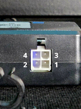
The bed control unit outputs power and data via a standard Mini-Fit 4-pin (2x2) Male plug directly on the control box.
When looking directly at the pins on the bed’s control module with the plastic latch hook facing UP:
- Top Row (closer to the latch):
- Pin 4: Left cell (Square) : Not Connected (NC)
- Pin 3: Right cell (Beveled) : +29V Power Output
- Bottom Row:
- Pin 2: Left cell (Beveled) : UART Data (3.3V bidirectional line)
- Pin 1: Right cell (Square) : GND
Tip: Always double-check the pins with a multimeter before connecting the hardware to prevent frying the board!
(Mini-Fit male connector pinout for reference)
2. Connection Settings & Sync
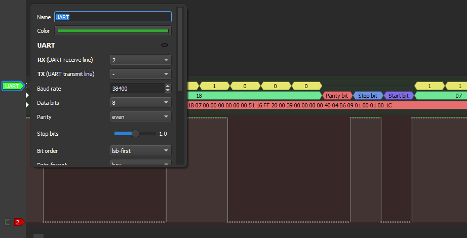
- UART Setup: 38400 baud, 8E1 (8 data bits, Even parity, 1 stop bit).
- Bus Type: Strictly bidirectional (half-duplex single-wire) with 3.3V logic levels.
- Sync: Frame synchronization relies on an idle line timeout. The bed transmits its status packets periodically every 139ms. In the testing code, the transmitter waits for at least a 5ms “silent window” on the bus after the bed finishes broadcasting before injecting TX bytes.
(PulseView capture demonstrating the UART decoder settings and a sample packet)
3. Power Supply & Voltage Regulation
- The bed’s control unit outputs 29V. Standard cheap DC-DC buck converters (like the ultra-popular Mini-360 modules) will not work because their maximum input voltage limit is usually capped at 23V-24V. A step-down module rated for at least 32V (with safe headroom) is required, such as WeAct modules based on the LGS5148 chip.
- In the test setup, a 5V regulator was used first to drop the voltage. Then, the built-in LDO on the ESP32 board dropped it from 5V to 3.3V.
- Why this is better: A dual-stage regulation approach provides better voltage smoothing and overall power stability for the ESP32’s sensitive Wi-Fi and Bluetooth RF stages. Additionally, if the main buck converter fails, the 5V intermediate stage serves as an extra layer of protection, preventing 29V from instantly frying the ESP32 chip.
4. Packet Format (Bed Status / RX)
- Byte 0: Packet length
- Byte 1: Source Address (
0x07indicates the bed) - Byte 2: Button Pressed/State mask (can be combined):
0x01= Head Up0x02= Head Down0x04= Foot Up0x08= Foot Down
- Byte 3:
0x10= Zero Gravity Button Pressed - Byte 5:
0x08= Flat Button Pressed - Bytes 18-19: Head Position (Little Endian:
Byte 19 << 8 | Byte 18) - Bytes 20-21: Foot Position (Little Endian:
Byte 21 << 8 | Byte 20) - Bytes 22-23: Head Load/Current (Raw units) (Little Endian:
Byte 23 << 8 | Byte 22) - Bytes 24-25: Foot Load/Current (Raw units) (Little Endian:
Byte 25 << 8 | Byte 24)
*Note: The purpose of the remaining bytes is unknown. They might show data on other models (like massage functions). If anyone figures any of them out, contributions in the comments are highly welcome!
Important Note on Position Telemetry:
The head and foot positions (Bytes 18-21) are purely virtual. The bed control unit has no physical position sensors; it estimates the values based on motor run time and current load.
Because of this, the position values can drift over time if the motors are not regularly recalibrated. To reset and sync the positions to zero, the bed must either be driven via the “Flat” button or the down button must be held for a few seconds after the bed fully bottoms out. Any automation software will likely need to account for this drift.
Additionally, there is no feedback for the maximum travel limits. To find the upper bounds for a specific bed, the head and foot must be manually driven to their maximum positions to record those raw values.
5. Checksum (CRC) Algorithm
The last byte of the packet is always the CRC. It is calculated as an inverted 8-bit sum (1’s complement) of all preceding bytes.
- To generate (TX): Calculate the CRC and append it to the packet bytes:
crc = (~sum(packet_bytes)) & 0xFF
full_packet = packet_bytes + bytes([crc]) - To verify (RX): Summing all bytes including the CRC must always equal
0xFF:
sum(full_packet) & 0xFF == 0xFF
Verified Test Case:
18 07 00 00 00 00 00 00 00 00 FF 20 00 00 00 00 00 00 00 00 00 00 01 00 01 00 BF
Summing the first 26 bytes and applying (~sum) & 0xFF gives exactly BF.
6. Sending Commands (TX Logic)
To send commands, the exact same packet layout is used. The source address for the transmitter must be 0x01.
Packets must be sent continuously, transmitting them in between the bed’s broadcasts. Specifically, the system should listen for the bed’s packet, wait for the 5ms silent window (idle line timeout) mentioned in Section 2, and then immediately inject the command packet into the bus.
Here is the payload structure for commands.
Note: The first byte 01 is the transmitter’s source address (included for clarity). Length and CRC are NOT included in the hex strings below - the Length byte must be prepended and the CRC byte must be appended at the end:
01 00 00 00 00 00: Full STOP01 00 10 00 00 00: Zero Gravity01 00 00 00 08 00: Flat01 01 00 00 00 00: Head Up01 02 00 00 00 00: Head Down01 04 00 00 00 00: Foot Up01 08 00 00 00 00: Foot Down
Important TX Behavior:
- Keep-Alive: The motor only runs as long as the button mask command is repeatedly sent.
- Stopping: To stop the bed instantly, the “Full STOP” command must be sent (a packet with all zeros in the button fields, as shown above).
- Safety Timeout: If the command transmission stops but the explicit “Full STOP” packet is not transmitted, the bed will run for a short guard timeout and then stop automatically for safety.
TODO / Known Challenges
Here are the specific hardware and software hurdles that still need a clean, compliant solution (and why a ready-to-use component/code has not been released yet):
- Single-Wire UART in ESPHome (Hardware/Driver level): I performed all my tests on an STM32-based board because it natively supports single-wire half-duplex UART out of the box. The ESP32 hardware supports this too, but I couldn’t find a clean way to configure a native single-wire bidirectional UART within ESPHome. Right now, the separate RX and TX lines must be combined into a single wire using a hardware Schottky diode workaround (connect the diode with the cathode facing the ESP32 TX pin, and the anode connected to the shared RX/Data bus line). A proper ESPHome software fix for half-duplex UART is needed here.
- The “Press-and-Hold” Problem (HA Frontend level): Because the bed requires a continuous stream of packets to keep the motor running, mimicking an active button hold from the Home Assistant frontend is a known pain point. In a vanilla HA setup without deep modifications, making a UI button act like a true momentary switch (transmit keep-alive packets while pressed, send “Full STOP” on release) is extremely difficult to do cleanly.
- The ESPHome Component Architecture (Code level): This is where I ultimately lost my motivation. I actually built the core integration using a custom state machine. It perfectly synced with the bed’s frames and handled the entire workflow using YAML lambdas. On top of that, an
esp32_ble_servercomponent was even added so that the hardware emulated the original Bluetooth module. This allowed official phone apps to connect and control the bed seamlessly alongside Home Assistant. It was remarkably easy to implement, but - as expected - everything was wrapped in lambdas. It worked absolutely fine, but apparently, writing code this way is “out of fashion” now according to the latest ESPHome guidelines. Today, to do things the “proper” way, everything is expected to be wrapped into a fullexternal_componentwith overcomplicated Python code-generation. Digging into those messy and non-obvious Python boilerplates just to finalize the entire project was a massive turn-off.
If anyone is enthusiastic enough to brave the modern ESPHome guidelines and wants to take this state machine logic and wrap it into a proper external component, feel free to use this data! I’d love to see someone finally bring this to a clean release.