Ok, I’m just testing with your template and no equipment connected. I have copied your template. So i cant understand why i have 0% on all negative angles
I’ll leave it running for a few days to get a better understanding of the figures i think
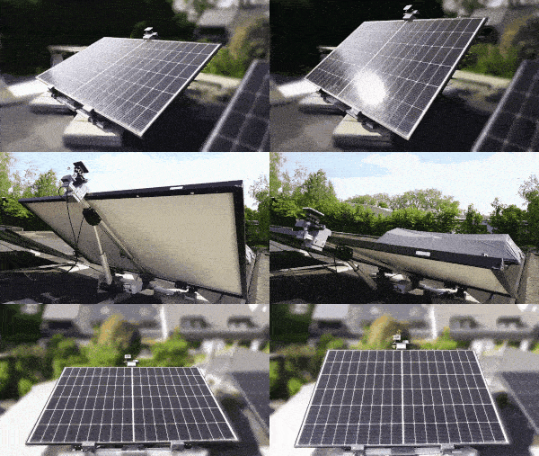
Because if you look at the pictures of the original post you will see the panel can only go flat or it can go up. So the minimum tilt angle is something like 0 degrees. So 0 degrees is 0%, -10 degrees, -20, -30 are also 0% etc. It makes sense ![]()
Hi Guys,
I do not really have a question just wanted to share what I made (and return what I learned also based on the information here).
The last year I was working on the “Sunchronizer S1”. A single axis solar tracker that can be used with “standard” 400W solar modules. The custom parts can be 3D printed.
Long story short: I documented the project at the following locations:
- Hackaday .io: Sunchronizer S1 - Elevation Axis Solar Tracker | Hackaday.io (Here you can also find the link to the ESPHome config)
- Nerdiy .de (my blog): Sunchronizer S1 - 400W solar tracker for elevation axis
The ESPhome configuration is WIP but works already pretty good for the single axis version. I plan to extend the single axis version to a dual axis tracker, therefore there are already some codesnippets prepared in the ESPHome-config. Maybe you can use some of the things. ![]()
If you need anything, just let me know. ![]()
Best regards
Fab

Great project. If I understand correctly you are tracking the sun with lux sensors rather than using the mathematical tracking I used here right?
Thanks.
Yes and no. ![]()
Currently the sun tracking is based on the mathematics based on the sun azimuth and elevation angle (and time of course).
(For that purpose I also integrated a GPS receiver to get time and position independently from network access. But thats another story…)
The Lux sensor actually escalated a bit to a project in a project. I started to design a solar tracking sensor called “SolSpot” (More info here: SolSpot - A universal light sensor for solar tracker setups | Details | Hackaday.io) for two reasons. One was that the direct tracking would be “better” than the calculated tracking (which is of course wrong, especially when you consider the additional amount of work/material). The other one is that I would also try to cover the low light cases when the sky is cloudy. Based on my tests/experience its best to put the panel as flat as possible.
Next step is to develop an algorithm that uses the data from the lux sensors and from the GPS sensor to calculate the best angle possible.
So the whole sensor situation is still under test and I want to check whats working best/most reliable. ![]()
If you have any ideas or feedback let me know. ![]()
Nice project…I was trying to set up a solar tracker with Ha,but had problem with N/S,because Ha dont use - for south and + for North.
So i went for another Arduino solution,but i can send Rest command by HA to the tracker to control it…for example Wind Parking…or shadow parking using an external light sensor.
I my project I use an Esp32 ,a gyro and a RTC module with battery to save setting when no electricity.
Annoied from Dupont Cable i decide to create and print an Esp32 board with a Gyro and Rtc Module connector,so they can be replaced and use different Gyro model,have external I2c pin to connect Gps or Lcd screen…and have Terminal screw for better safety.
Input Voltage 12 or 24 volt…
This board can be used also with your project to make things more easy and reliable.
I post a pic,if can help.
Well you can always correct it. I dont understand why you would need an arduino for that.
@ans-gw I think I know this photo. Did you find any further developments?
i mean arduino ide for programming…
Hello, I bought a system from ecoflow and I’m not satisfied.
The mount is OK, but the control isn’t.
I want to solve this problem via my home automation system. Is there a convenient solution? I’m very bad at programming.
I’d like to keep the bracket. Replace the chain drive with one with Tuya.
https://www.google.com/aclk?sa=L&ai=DChsSEwiQiq-etbWOAxVIWpEFHc_mNhkYACICCAEQGhoCbHI&co=1&gclid=CjwKCAjw7MLDBhAuEiwAIeXGIQsQksLWIUsctrPltVOSRP9rcXOVo1ABxvaQvefOmtF-aH4-WX49GxoCMggQAvD_BwE&sph=&cid=CAASJeRow816cBGtWFJIGwSIobg8Ggl3OMBOpP6lM7i5qUvkzshWN88&cce=1&sig=AOD64_0sn5B01ZwP38aTGHoDbBHlyC_V-w&ctype=70&q=&ved=2ahUKEwi1uqqetbWOAxUKEhAIHUp7JPUQwg8oAHoECAkQNw&nis=8&adurl=
Kind regards
hi, could you create a topic for this and specify exactly what hardware you have and what you want to achieve? Please do not use tuya equipment, they are unreliable and tend to have lots of issues with home assistant.
where did you bought this board ?
New Board and software are ready.I put on Ebay:Solar Tracker 2 or 1 Axix Gps Tracking System WiFi Control App Shadow Park set.
This software version have new Shadow Park function:
Es:if in the morning you have shadow on the panel,you can set a different angle and set the time tracker must keep that angle…after that time tracker will return on the original tracking position.
This board have a connector for SH1106Wire display with this pins. in order: SDA-SCL-GND-3.3V.
Good morning, how is the integration in HA going?
I would like to replace my EcoFlow with it.
Is there already a project with it?
The board looks very interesting.
Best regards
Hey guys,
just throwing my project as possible alternative in here…
The firmware of the sunchronizer is fully based on esphome and therefore 100% homeassistant compatible. (Regarding the ecoflow problem you need to tinker abit I guess…)
You can find everything neede here: GitHub - Nerdiyde/Sunchronizer: Sunchronizer is a 3D printable dual axis solar tracker for "standard" ~400W solar panels · GitHub