In collaboration with @Homeotte41 I have been working on a solar tracker project for Home Assistant. Since the technical details could be useful for other projects that involve tracking the sun (see my post here: Incident Angle of Sunlight) I share them here below.
@Homeotte41 made a nice video to showcase the mechanical design he made to change the tilt angle of the panels:
https://www.youtube.com/shorts/CI7dLNPx9DM
More pictures of the PV installation can be found at the bottom of this post.
Here is a graph showing the power output over a whole day, can you guess which graph has implemented the tracking system? ![]()

Horizontal single axis trackers (HSAT)
There are many types of single and dual axis solar trackers, and if you look online you can find several projects that use them. The principle is simple, you want to maximize the amount of solar energy that you collect, and the best way to do that is to point your solar panels directly at the sun to maximize the direct beam radiation.
Typically this is done by fitting a set of sensors to the panel that try to 'find' the sun in the sky, but with the HA sun platform we have exact knowledge of solar azimuth and elevation angles based on our position and time of day. Therefore we will control the tracker via the elevation and azimuth HA calculates for us based on our latitude, longitude and time of day.
(in mathematical terms, we will align the normal vector of the panel with the sun's rays)
Horizontal single axis trackers are nice because they are relatively simple to build and therefore cheap. You can find more information about them at [1].
[1] HSAT Trackers: Design and Application
Optimizing the incident angle θ
The math is largely based on this paper by the National Renewable Energy Laboratory:
[2] Rotation Angle for the Optimum Tracking of One-Axis Trackers
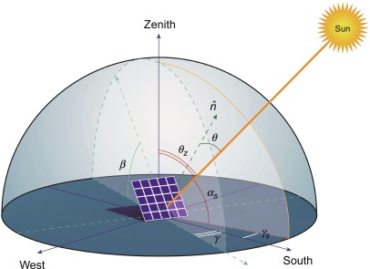
The math is a bit tedious to explain but in principle it only involves trigonometry and some basic derivative calculus. In general, we try to minimize the Angle of Incidence (AOI) θ between the sun's rays and the panel's normal vector by setting the panel's rotation angle R such that the AOI θ is minimized. The following equation describes the AOI:
cos(θ) = cos(β) cos(θz) + sin(β)sin(θz)cos(γs -γ)
Where:
- β is the surface tilt angle
- γ is the surface azimuth angle
- θz is the sun's zenith angle (which we get from HA)
- γs is the sun's azimuth angle (also get from HA)
To minimize θ we can maximize cos(θ), which reaches it's maximum for θ = 0 and then cos(θ) = 1.
Because for a horizontal axis tracker the tilt of the rotational axis is always zero and the rotational angle R has a range of [-90°, +90°] the general equation for the optimal rotation angle found in the paper can be simplified to (see section 5 of [2]):
R = arctan[tan(θz)sin(γs - γa)]
Where γa is the azimuth angle of the tracker axis, which we find by looking at google maps and measuring the angle between the rotation (tracker) axis and the north-south axis. Note that the rotational axis angle is perpendicular to the surface azimuth angle γ. In the below image our tracker mode is image (c).

solar_tracker_angle:
  friendly_name: Solar tracker angle
  unit_of_measurement: 'degrees'
  value_template: >

    {% set deg2rad = pi/180 %}
    {% set rad2deg = 180/pi %}

    {% set sun_azi = deg2rad * state_attr('sun.sun', 'azimuth') %}
    {% set sun_zen = deg2rad * (90 - state_attr('sun.sun', 'elevation')) %}
    {% set rot_azi = deg2rad * (58-90) %}

    {% set night_def_angle = states('input_number.solar_tracker_default_angle_at_night') | int(-10) %}

    {% if state_attr('sun.sun', 'elevation') < 0.1 %}
        {{ night_def_angle }}
    {% else %}
        {{ rad2deg * atan(tan(sun_zen) * sin(sun_azi - rot_azi)) }}
    {% endif %}
See above YAML code for the template sensor in HA to calculate R. First, we convert the azimuth and elevation angles from degrees to radians. Then we calculate the azimuth angle of the tracker (rotation) axis γa. The panels point 58° clockwise from north but because the rotation axis is perpendicular to the panels we subtract 90° from that, see picture above. For our calculations we require the zenith angle of the sun θz = 90° - θelev, since it's with respect to the vertical axis instead of the horizon.
Then finally we check whether the sun is below or above the horizon, since tracking in the night is not very useful. If the sun is below the horizon we simply take the default value which can be set by an input_number helper entity in HA. We choose to keep the panel flat during the night so the default angle should be equal or below the minimum angle of -4°. The final value R is given in radians and then converted to degrees. We generally work in radians because the trigonometric functions in jinja templates expect radians as input.
Converting panel tilt R to linear actuator extension d
In order to tilt the solar panels we use a linear actuator from AliExpress: VEVOR 12V Solar Tracker Linear Actuator. The actuator is mounted on the back of the panel and pushes the panel up and down. The goal now is to find a linear actuator extension d, that gives a certain tilt angle R, that minimizes the AOI θ. The actuator has a stroke length of 500mm, a minimum length dmin = 605mm when it is fully retracted and a maximum length of dmax = 1105mm when it is fully extended.
We make a graphical model of the actuator and the panel, and then we can use the model to find the extension d that gives tilt angle R. The math might look at bit daunting at first but it's actually just the cosine rule and some applications of Pythagoras, most people will have had both in high school. First L1, L2, L4 and L5 were measured, and then L3 and L6 can be computed using Pythagoras. We also have to compute a few fixed angles using atan. Everything is explained quite well in [3] so I highly recommend to read if you are looking to built this yourself.


YAML template sensor code to calculate d from R:
solar_tracker_act_perc:
  friendly_name: Solar tracker linear actuator percentage
  unit_of_measurement: '%'
  value_template: >

    {% set deg2rad = pi/180 %}

    {% set L1 = 740 %}
    {% set L2 = 1185 %}
    {% set L4 = 1290 %}
    {% set L3 = sqrt(L1**2 + L4**2) %}
    {% set L5 = 75 %}
    {% set L6 = sqrt(L5**2 + L2**2) %}

    {% set d_max = 1105 %}
    {% set d_min = 605 %}

    {% set alpha_k = atan(L1/L4) %}
    {% set alpha_c = atan(L5/L2) %}

    {% set alpha_max = acos((L3**2 + L6**2 - d_max**2) / (2*L3*L6)) + alpha_c - alpha_k %}
    {% set alpha_min = acos((L3**2 + L6**2 - d_min**2) / (2*L3*L6)) + alpha_c - alpha_k %}

    {% set alpha = deg2rad*(states('sensor.solar_tracker_angle')|float(0)) %}
    {% set alpha_lim = max(min(alpha, alpha_max), alpha_min) %}
    {% set alpha_d = alpha_lim - alpha_c + alpha_k %}

    {% set d = sqrt(L6**2 + L3**2 - 2*L6*L3*cos(alpha_d)) %}

    {% set d_lim = max(min(d, d_max), d_min) %}
    {% set d_perc = 100*(d_lim - d_min) / (d_max - d_min) %}

    {{ d_perc | round(0) | int }}
To compute the maximum and minimum angles αmax and αmin that the panel can rotate we can use the cosine rule with the maximum and minimum length of the actuator as input. We then clamp the desired angle α to be between αmax and αmin. To compute the actuator length d that achieves the desired angle θ we can use the cosine rule again. Finally we convert the length d to a percentage of the total length of the actuator. So if the actuator is fully retracted the percentage is 0% and if it is fully extended the percentage is 100%, with a step size of 1%. Note that d is clamped to be between dmin and dmax again but this is technically not necessary due to the clamping of α, it's just a precaution.
[3] A simplified calculation method of electric linear actuators for single-axis sun tracker
Control electronics and ESPHome YAML
The control electronics consist of a relay board with an ESP8266 that runs ESPHome. The relay board switches the polarity of the 12V output to either extend or retract the linear actuator a certain distance. The distance depends on the on time duration of the relay. To find the time it takes to fully retract or extend the actuator we used a stopwatch, these values can be found in the below YAML as open_duration and close_duration. We also measured the stroke length in steps of 10% from 0% to 100%. We found this to be approximately linear (p/m a few mm) and thus accurate enough. See below picture for the box that houses the relays. The ESP8266 addon module is not present in this picture, but it is placed left of the relays on the 8-pin header.

button:
  - platform: template
    name: "zonnepanelen Open"
    on_press:
      - switch.turn_on: relay1
  - platform: template
    name: "zonnepanelen Close"
    on_press:
      - switch.turn_on: relay2

switch:
  - platform: gpio
    id: relay2
    pin:
      number: GPIO0
      inverted: true
      mode: OUTPUT_OPEN_DRAIN
    restore_mode: RESTORE_DEFAULT_OFF
    name: "zonnepanelen Close"
    interlock: [relay1]
  - platform: gpio
    id: relay1
    pin:
      number: GPIO2
      inverted: true
      mode: OUTPUT_OPEN_DRAIN
    restore_mode: RESTORE_DEFAULT_OFF
    name: "zonnepanelen Open"
    interlock: [relay2]

cover:
  - platform: time_based
    name: "scherm Control"
    id: cov_pond_skimmer
    open_action:
      - switch.turn_on: relay1
      - switch.turn_off: relay2
    open_duration: 65s
    close_action:
      - switch.turn_off: relay1
      - switch.turn_on: relay2
    close_duration: 61s
    stop_action:
      - switch.turn_off: relay1
      - switch.turn_off: relay2
    assumed_state: false
Since the relay board has active low inputs our ESPHome YAML has to invert the outputs. The interlock option ensures that only one of the two relays can be on at the same time. The mode: OUTPUT_OPEN_DRAIN option ensures that the GPIO can only assume a high impedance (hi-z) state or low state which works great with active-low inputs. The restore_mode: RESTORE_DEFAULT_OFF option attempts to restore the ESP state when it boots and if it can't ensures that the relays are off. The linear actuator is modelled as a cover entity in HA.
Actuator control automation
The cover entity gives us a very convenient way to control the actuator, to set a certain actuator length d we simply call the service cover.set_cover_position with the stroke length d as a % in the range [dmin, dmax] as the position argument. The automation is triggered anytime the input sensor entity sensor.solar_tracker_act_perc changes. The automation then calls the service cover.set_cover_position with the input number as the position argument. You can find the automation YAML code below. It's pretty simple but could always be improved if needed, for example you could close the panels during a storm based on the wind speed.
alias: test_solar_angle
description: ""
trigger:
  - platform: state
    entity_id:
      - sensor.solar_tracker_act_perc
condition: []
action:
  - service: cover.set_cover_position
    target:
      entity_id: cover.scherm_control
    data:
      position: "{{ states('sensor.solar_tracker_act_perc') | int(0) }}"
mode: single
PV installation images
Some nice images taken by @Homeotte41 to give you a better idea of what it looks like:


PVLib simulation
In order to estimate the energy gain of the solar tracker we can use the PVLib python library to run a small simulation. Special thanks to Kevin from PVLib google group for help setting this up.
With all default parameters the AC power plot on a clear day in june, with a 1kW system, looks like this:

From the plot it's visible the tracker collects more energy, especially during the morning and late afternoon. The total energy gain is about 20% for this day. In reality the energy gain will be quite a bit lower, because in reality the tilt angle is limited to about -4° towards south-west which limits the efficiency in the afternoon. But we still see we are able to improve efficiency during the morning and early afternoon compared to a fixed system.


