Finally decided to automate my sprinkley system and settled on the PSF-B04 purchase via ebay.
Using the following guide as a start was able flash with Tasmota firmware:
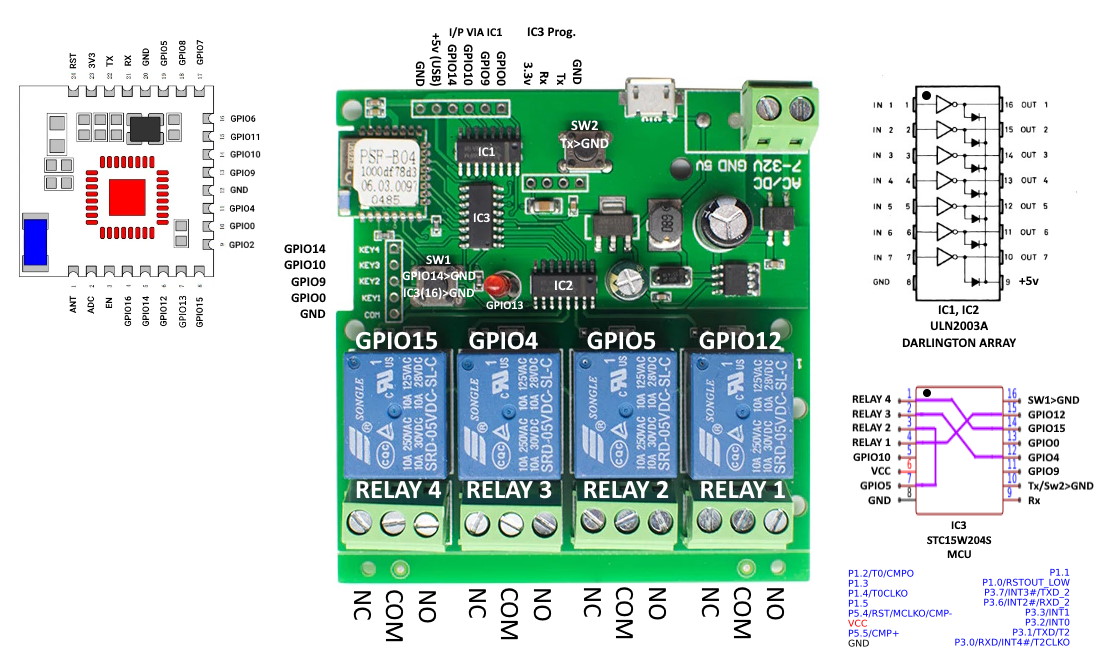
Only to add to the above notes, instead of soldering necessary programming wires directly to the ESP8285 which can be challenging, GND, GPIO0 and 3.3Volts are easily accessible on other parts of the board as I’ve marked below , in addition GPIO0 and GND are conveniently position next to each other on a header.
Initially purchased two of the boards, one worked perfectly that is all 4 relays could be switched on at the same time but the other wouldn’t play ball. That is, switching on each individual channel on/off worked fine, but attempting to switch on all 4 relay channels would lose connectivity and device would reboot.
As I wouldn’t be switching on all 4 channels for my sprinkler system not an issue, but curious as to why this was occurring. Also purchased an additional board as a spare, but it also exhibited the same fault.
After eliminating several possible causes, power, shorts and PCB track variances between the boards nothing obvious stood out.
Curiously couldn’t understand the purpose of a mystery chip as shown circled above with all marking removed. All 4 relay output pins from the ESP8285 entered this chip and another 4 pins went to the digital input pins of the ULN2003, therefore not sure what the purpose of this chip performed and couldn’t see any reason why if removed and bypassed the board would still function the same….So I did!
Once mystery chip was removed and using the now free chip pads and wired as shown below was able to drive the ULN2003 directly without any issues and able to then switch on all 4 channels.
Hence still wondering what the purpose the chip serves but suspect it’s some sort of microprocessor/buffer with maybe a firmware bug as one of the three did work??
Be interested if anyone else has more info. on this chip.
Thanks! It helped me.
After upgrade to tasmota, I had not working device at all (was not able to control relays).
After the bypass chip hack everything is fine. Thanks for sharing!
Hey there !
I know it’s an old thread but it has been very useful to me in order to add it to my HA installation.
It’s been used to control 4 solenoid valves, works like a charm as I can use the same power supply for the solneoid and the board (DC 12V)
Now I wanted to go a bit further and add a flow meter (FSP300A), that I planned to hook onto a free GPIO of the board… but after reading the original article, and this one, I got to the conclusion that there were no available GPIO to hook a pulse_counter ?
I tried to use the RX pin with no luck (as I only need the TX to still get the logger).
Hey, thanks for your reply !
I’d rather stick to ESPHome as all my devices are based on it.
I actually managed to patch my flow meter using the onboard 3.3v, GND and GPIO14 (Key4 on the board).
Now everything is working flawlessly and I only need one 12vDC to power the board, the 4 solneoids and the flow meter (rated 5v but works perfectly in 3.3v hence pushing back only 3.3v to the GPIO)
Flash my module with Tasmota following the instructions described in this thread.
As has happened to other people, no relay responded.
The unknown chip, on my board is readable as 15w204, a microcontroller with 8051 architecture.
The purpose of this 15w204 is to learn the remote control keys, as I didn’t want to lose the functionality of the remote control, I didn’t unsolder the 15w204, I simply cut pins 1,2,3 and 4 and joined them with wires to pins 15, 14,12 and 7 according to @Robert Galleiso drawing.
Now everything works perfectly.
After some tinkering I can confirm the MCU chip is an STC15W204S - I got it to talk to the STC programming software using a USB/TTL interface module. However, there doesnt seem to be a way to download the existing contents of the chip to reverse engineer the logic.
I think there may be an error in your internal routing diagram … if you trace Relay 4 (left) through the darlington chip it goes to pin 1 of the MCU. It is controlled by GPIO15 which is connected to pin 14 of the MCU. Of course you can configure the GPIO in Tasmota, so it doesnt matter too much.
Whilst I was at it, I traced the other pins of the MCU to the two headers, one via the other darlington chip. I think this header was for a remote interface, so GPIO0, 9, 10 and 14 will also have some unknown function within the MCU.
In summary, to use GPIO0, 9, 10 and 14 for some other functions via the left hand header, it is probably safer to remove the MCU and create hard links like youve done. Ive summarised my findings in hte attached sketch.
Interesting, I haven’t checked and compared to your findings. But it must be correct as it works.
Maybe a couple of different variations of the board floating around??