After some tinkering I can confirm the MCU chip is an STC15W204S - I got it to talk to the STC programming software using a USB/TTL interface module. However, there doesnt seem to be a way to download the existing contents of the chip to reverse engineer the logic.
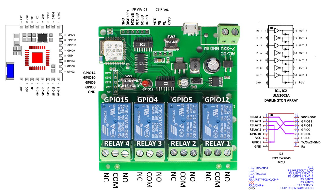
I think there may be an error in your internal routing diagram … if you trace Relay 4 (left) through the darlington chip it goes to pin 1 of the MCU. It is controlled by GPIO15 which is connected to pin 14 of the MCU. Of course you can configure the GPIO in Tasmota, so it doesnt matter too much.
Whilst I was at it, I traced the other pins of the MCU to the two headers, one via the other darlington chip. I think this header was for a remote interface, so GPIO0, 9, 10 and 14 will also have some unknown function within the MCU.
In summary, to use GPIO0, 9, 10 and 14 for some other functions via the left hand header, it is probably safer to remove the MCU and create hard links like youve done. Ive summarised my findings in hte attached sketch.
2 Likes