Hi All,
I’m new to the ESP world and have had some success building esp8266 based controls for LEDs and 12v fans.
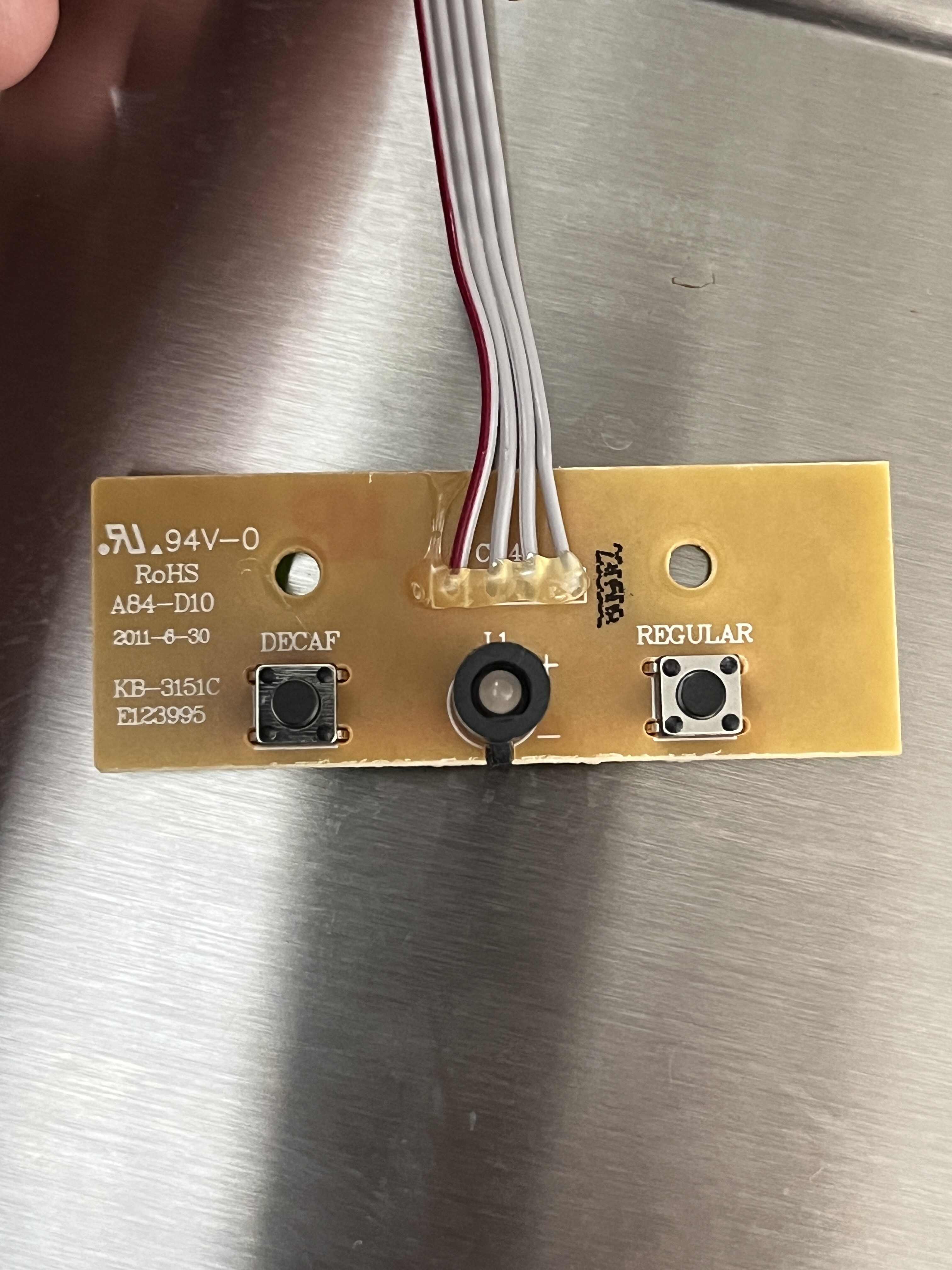
I am running into an issue with my coffee maker.
I through that the simple mechanical push button switches would make it very easy to control, but they are not wired to close a circuit and provide 5v back to the coffee maker.
The switches have 5v DC when they are pictures.
Any ideas for how I can wire this?
Ideally I would like to be able to start the brewing on a timer or from the Home Assistant button.
Eventually I would like to have a notification sent when the LED turns off as well. Or I may just set up a timer in automations.
Optocouplers or logic level converter would both work. If the 2 buttons do indeed use 5v, you can wire that straight to an esp8266 NodeMCU, the gpio pins are 5v tolerant unlike the esp32 that isnt 5v tolerant.
How you wire these switches will depend on how theyre wired now. On one side of the switch you should have 5v or Ground and nothing should show up on the opposite side of the buttons. You need use your multimeter and figure out if those buttons when pushed do they close the 5v part of the circuit or do they use ground. Your finding out if these buttons use Active High or Active Low. Once you know that you know which way to wire them and if you need pullup or pull down resistors.
So, active high and active low are the 2 ways a simple switch like this works. If you have 5v at the switch when its depressed(Off) that means its active Low. So with your esp board and depending on which esp board you use. Youre going to want to connect a gpio the the 5v side of the switch and ground to ground. In active low there will be a positive voltage at the gpio and your going to want to watch for it to go Low or to ground and thats how you know when its active(on).
You arent wanting to monitor the state of the switches though right? You basically want to push those switches from HA?
Thank you so much for the explanation.
I want to be able to “press” the switches in HA and maybe monitor the state of the LED - but I haven’t thought that out yet. Still trying to wrap my head around the switches needing to be pulled down.
Not exactly. It took me a little time to wrap my head around this too so dont worry about it. If you put your multimeter leads on both sides of a button and you get 5.0v and when you push the button it goes to 0v. Thats active low because when the switch is pressed/on it goes low/0v.
It seems counterintuitive, i know. A lot of people have the misconception that when a button is presssd, the circuit is closed and a positive voltage is the result. Active low is probably the most common. Its used in buttons, switches, sensors and youve probably seen it on single and multichannel relay modules. That black jumper with an “H” and “L” on each side of the jumper. Thats so you can choose how the relay is triggered, high voltage or low voltage.
To be able to switch these from HA, youll need something like a relay that can open and close a circuit. A relay wouldnt be my first choice though. They’re bulky and make annoying clicking sounds. It really depends on how much room youve got inside to work with.
in going to have a educated guess and say that those tactile switches aren’t going to be switching high loads, they are going to be connected to a micro controller in the coffee machine.
the thing you will have to watch is the voltage, 5v is too high for most ESP inputs.
so your not going to need a big relay for switching. a logic level shifter should suffice to drop the 5v to 3v to your input. and in the reverse direction it could also pull the pin low to “press” the button.
have a read of this article, it will give you the info you need. leave the HV pin disconnected though, at this is already on the motherboard of the coffee machine… and why the wire is 5v when the button isn’t pressed. edit: just remembered i had to remove the resistors on the HV side for this to work too, otherwise both buttons get pressed. https://learn.sparkfun.com/tutorials/bi-directional-logic-level-converter-hookup-guide/all
for checking the LED you may need to use a voltage divider, pretty simple to implement, its also worth checking if there is any PWM on the pin to adjust its brightness, may cause some issues with sensing if you don’t know about it… just use some bigger debounce values if you have issues.
edit 2 :
a quick and dirty sketch, these are really common super duper cheap level shifters
available everywhere… remove the components with the red x and reuse one of the resistors to bridge across where the fet was and you get a nice voltage divider on the same board. (note the use of the hv pin just so the pads are in the right pace for the voltage divider). led status is probably best done with a analog read of the pin and if its above a certain value then its on, what value this is you will have to work out by seeing what’s reported in each state
Nice! You brought up some good points that i overlooked. Using ADC for the led instead of just logic levels. I suspect both ways would work fine but, ADC is probably the better way.
Modifying transistor based logic shifters to make a voltage divider is flipping brilliant. Idk how ive never head of this before but, i like it.
FYI
The esp8266 and more specifically the NodeMCU dev boards are 5v tolerant on the gpios. There may be other esp8266 boards 5v tolerant as well but im not sure which ones. I do know the NodeMCU is and i use one with my Wiegand26 keypad/rfid reader. The data pins on most of these keypads are 5v and can be wired directly tl the nodemcu.
if the pins are 5v tolerant then they can just be connected directly
configure the pin schema as INPUT_OUTPUT_OPEN_DRAIN for the button pins so you can read the state and drive them low to press the button.
see if the LED status can be read correctly with a normal binary input, if so great, otherwise analog may need to be used. just be careful as i dont think the analog in’s are 5v tolerant… but i may be wrong…
I’m still learning ESPhome and how things work too, but my understanding is when you setup a gpio in esphome you normally use pin schema to set the gpio number, inverted, pullups etc.
so… you are going to be wiring up an esp to a circuit to pull the line low to press the button, there is really only 2 states, active and inactive,
with the normal OUTPUT it will pull the pin high or low depending on the state and inversion
with OUTPUT_OPEN_DRAIN or INPUT_OUTPUT_OPEN_DRAIN
when inactive its like there is nothing connected, and when active it will pull the pin up or down depending on inversion.
if you were to use OUTPUT to press the button you would set the pin low, to not press the button you set the pin high, when the pin is set high if someone pressed the button the button would need to short out the current from the coffee machine pullup and also the ESP drive current ~20mA and without a resistor in the circuit i think something would break… likely the esp output.
whereas if you set it up as open drain its just in a floating state when inactive so the button can pull the pin down and it wont have to short out any current from the pin.
i think you will use inverted = true, but you may want to setup some led’s, resistors and some buttons on a breadboard just to confirm how it all works before hooking it up. i find simulating the circuit you are hooking up to easier… at the desk infront of the computer where you can see is way easier than pulling apart the machine fitting the esp and then trying to see whats happening when its suffed down a little gap in the machine.
and because you can use the pins as inputs at the same time, you can read the state of the buttons too, so you will see if someone presses the button to make a coffee. logging how many coffees it takes to do these fun projects would be an interesting statistic! i’m probably up to about 500 on my current project haha… it has been ongoing for 6months now
Chris,
That’s awesome. Thank you very much for the patient and very clear explanation! I cannot wait to try it.
I’m currently at 12 coffees on this project and I’ve taken the coffee maker apart 2 times
I will play with the breadboard this evening to see if I can get the code working. Definitely want to make sure I get it right so I don’t fry my coffee maker