For some additional information, below is the output from the Pool-Pi logs. The highlighed section shows the command sent from the Pool-Pi web UI for the blower circuit. Unfortunately this does not turn on the circuit. The code makes 10 attempts, then errors out but the UI is stuck in a “loading” screen.

The below log is a python script to monitor the serial activity and shows activity from when the blower circut was physically pressed on the aqualogic panel. The yellow highlighted output matches the command from above and the program configuration. I’m not sure what the blue highlighted command is but matches the DLE\STX\FRAME_TYPE_LOCAL_TOGGLE syntax from the code as if it were initiated from the local panel.
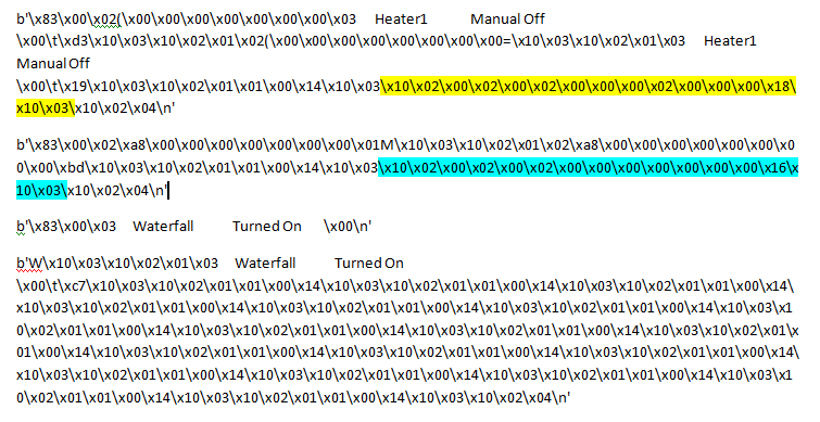
This suggests to me that the rs485 adapter is sending commands from the pool-pi software; the program is seperately receiving commands from the panel (as well as display and LED info) and the 2 match.
What I can’t understand is why it isnt working 
Curious… which Hayward panel are you connecting to and are you sure it can receive commands?
Back in 2016 I had a Hayward Prologic P4 which has all the same features as my Prologic PS4 except it could not receive commands. I could read all events, but it just ignored me.
Also… I encode all my commands as from a remote keypad. Seems when I encoded as a local keypad I was ignored.
FRAME_DLE 0x10
FRAME_STX 0x02
FRAME_TYPE_REMOTE_WIRED_KEY_EVENT b’\x00\x03’
key.value.to_bytes(4, byteorder=‘little’)
key.value.to_bytes(4, byteorder=‘little’)
crc.to_bytes(2, byteorder=‘big’)
FRAME_DLE 0x10
FRAME_ETX 0x03
Thank you for your help. I am pretty sure it is a PS-8. Below is a pic of the control panel

I have tried to change the frame type in the pool-pi program to the wired (x00/x03) and wireless (x00/x83) remote keypad structure, but I’m not sure if the checksum values are the same. I may just need to abandon the pool-pi option and give the HA code a try.

No, the CRC would be different as the CRC is += each byte starting with the DLE.
Just to make sure that we are flipping the same pancakes… here is the code that I execute for a successful LIGHTS command.
snippets from my code…
from enum import IntEnum, unique
@unique
class Keys(IntEnum):
    RIGHT = 0x0001
    MENU = 0x0002
    LEFT = 0x0004
    SERVICE = 0x0008
    MINUS = 0x0010
    PLUS = 0x0020
    POOL_SPA = 0x0040
    FILTER = 0x0080
    LIGHTS = 0x0100
    ..
    SUPER_CHLORINATE = 0x04000000

..

command='lights'
KEY = Keys[command.upper()]

..

FRAME_DLE = 0x10
FRAME_STX = 0x02
FRAME_ETX = 0x03
FRAME_TYPE_REMOTE_WIRED_KEY_EVENT = b'\x00\x03'

..

frame = bytearray()
frame.append(self.FRAME_DLE)
frame.append(self.FRAME_STX)
frame.append(self.FRAME_TYPE_REMOTE_WIRED_KEY_EVENT)
"""
Yes, the key encoding is doubled.
But if you were holding a key down, then on each 100ms it is held, the second word is all 0s.
But I haven't tested that theory yet.
"""
frame.append(key.value.to_bytes(4, byteorder='little'))
frame.append(key.value.to_bytes(4, byteorder='little'))
crc = 0
for byte in frame:
    crc += byte
frame.append(crc.to_bytes(2, byteorder='big'))
frame.append(self.FRAME_DLE)
frame.append(self.FRAME_ETX)

""" send frame after KEEP_ALIVE """
Below is the command structure from the pool-pi code:
MAX_SEND_ATTEMPTS = 10  # Max number of times command will be attempted

DLE = b"\x10"
STX = b"\x02"
ETX = b"\x03"

FRAME_TYPE_KEEPALIVE = b"\x01\x01"
FRAME_TYPE_LEDS = b"\x01\x02"
FRAME_TYPE_DISPLAY = b"\x01\x03"
FRAME_TYPE_DISPLAY_SERVICE = b"\x02\x03"
FRAME_TYPE_SERVICE_MODE = b"\x03\x03"
FRAME_TYPE_LOCAL_TOGGLE = b"\x00\x02"

# Bitmask for LED updates
LED_MASK = [
    [
        (1 << 0, "heater1"),
        (1 << 1, "valve3"),
        (1 << 2, "checksystem"),
        (1 << 3, "pool"),
        (1 << 4, "spa"),
        (1 << 5, "filter"),
        (1 << 6, "lights"),
        (1 << 7, "aux1"),
    ],
    [
        (1 << 0, "aux2"),
        (1 << 1, "service"),
        (1 << 2, "aux3"),
        (1 << 3, "aux4"),
        (1 << 4, "aux5"),
        (1 << 5, "aux6"),
        (1 << 6, "valve4"),
        (1 << 7, "spillover"),
    ],
    [
        (1 << 0, "systemoff"),
        (1 << 1, "aux7"),
        (1 << 2, "aux8"),
        (1 << 3, "aux9"),
        (1 << 4, "aux10"),
        (1 << 5, "aux11"),
        (1 << 6, "aux12"),
        (1 << 7, "aux13"),
    ],
    [(1 << 0, "aux14"), (1 << 1, "superchlorinate")],
]

# Buttons where button/state is confirmed
button_toggle = {
    "service": b"\x08\x00\x00\x00",
    "pool": b"\x40\x00\x00\x00",
    "spa": b"\x40\x00\x00\x00",
    "spillover": b"\x40\x00\x00\x00",
    "filter": b"\x00\x80\x00\x00",
    "lights": b"\x00\x01\x00\x00",
    "heater1": b"\x00\x00\x04\x00",
    "valve3": b"\x00\x00\x01\x00",
    "valve4": b"\x00\x00\x02\x00",
    "aux1": b"\x00\x02\x00\x00",
    "aux2": b"\x00\x04\x00\x00",
    "aux3": b"\x00\x08\x00\x00",
    "aux4": b"\x00\x10\x00\x00",
    "aux5": b"\x00\x20\x00\x00",
    "aux6": b"\x00\x40\x00\x00",
    "aux7": b"\x00\x80\x00\x00",
    "aux8": b"\x00\x00\x08\x00",
    "aux9": b"\x00\x00\x10\x00",
    "aux10": b"\x00\x00\x20\x00",
    "aux11": b"\x00\x00\x40\x00",
    "aux12": b"\x00\x00\x80\x00",
    "aux13": b"\x00\x00\x00\x01",
    "aux14": b"\x00\x00\x00\x02",
}
Huh… The value for filter looks wrong, it is the same as Aux7. Octet 0 and octet 1 should be swapped.
Where is the code that builds the command and generates the CRC?
Here is what my encoded commands look like in some debug output:
menu
INFO:core:Sent: b'10020003020000000200000000191003'
DISPLAY__: Settings Menu

right
INFO:core:Sent: b'10020003010000000100000000171003'
DISPLAY__: Pool Heater1 [87_F]

left
CMD_SENT_:
INFO:core:Sent: b'100200030400000004000000001d1003'
DISPLAY__: Settings Menu

lights
CMD_SENT_:
INFO:core:Sent: b'10020003000100000001000000171003'
DISPLAY__: Lights Turned On
Yes sir, you are correct regarding the filter. I have made so many changes to the code, I had reverted back to the orgional code which had filter as /x00/x80. I have changed it back to /x80/x00 with a frame type of /x00/x03 but same results. Below are logs sending the filter command after updating.

Below are logs from the lights command which seems to match your lights command

Below is the code that builds the command and generates the CRC
# Manages flow when sending commands
class CommandHandler:
    parameter = ""  # Name of parameter command is changing
    target_state = ""  # State we want parameter to be in
    send_attempts = 0  # Number of times command has been sent
    sending_message = False  # Flag if we are currently trying to send a command
    last_model_timestamp_seen = 0  # Timestamp of last model (LED update) seen to ensure we witness a new model before attempting additional send
    full_command = b""  # Bytearray of full frame to send
    keep_alive_count = 0  # Number of keep alive frames we have seen in a row
    confirm = True  # True if command needs to be confirmed, false if not (menu command)

    def initiateSend(self, commandID, commandState, commandConfirm):
        self.confirm = commandConfirm
        if self.confirm == True:
            commandData = button_toggle[commandID]
        else:
            commandData = buttons_menu[commandID]
        # Form full frame to send from start tx, frame type, command, checksum, and end tx.
        partialFrame = (
            DLE + STX + FRAME_TYPE_LOCAL_TOGGLE + commandData + commandData
        )  # Form partial frame from start tx, frame type, and command.
        # Calculate checksum
        checksum = 0
        for byte in partialFrame:
            checksum += byte
        checksum = checksum.to_bytes(2, "big")
        partialFrame = partialFrame + checksum
        # If any x10 appears in frameType, data, or checksum, add additional x00
        self.full_command = (
            partialFrame[0:2]
            + partialFrame[2:].replace(b"\x10", b"\x10\x00")
            + DLE
            + ETX
        )
        self.keep_alive_count = 0
        self.sending_message = True
        self.parameter = commandID
        self.target_state = commandState
        self.send_attempts = 0
        return

    def sendAttemptsRemain(self):
        """
        Return true if we have more sending attempts to try
        Return false and stop command sending if we have exceeded max send attempts
        """
        if self.send_attempts >= MAX_SEND_ATTEMPTS:
            # Command failed
            logging.error(f"Command failed after {MAX_SEND_ATTEMPTS} attempts.")
            self.sending_message = False
            return False
        self.send_attempts += 1
        logging.info(f"Command send attempt {self.send_attempts}.")
        return True
@Daniel8192 @adamgranted
I am now attemptng to implement the HA integration with some of the custom code shared in this thread.
At this point I have cloned the base aqualogic code to /home/pi/aqualogic
Due to using a raspberry pi 2b, I had to install HA in docker. From what I understand, the HA aqualogic integration config does not allow entry of a hard wired serial device. My port is /dev/ttyAMA0. How do I get this added to the code/integration?
Also from what I’ve read, I need to create a custom_components aqualogic directory in HA and add the modified sensor.py and switch.py files to this directory.
Am I on the right track with this setup?
There's no reason your setup won't work - I'm using HA on Docker with no issues. You will need a ethernet to RS485 interface like the one I mentioned in post #401.
As far as the custom components, my forked version of the library (quoted below) outlines the steps in the description. Once you drop it into the custom_components directory, HA should just pick it up. Watch the HA server logs on restart and you should see it being recognized.
As far as the wiring goes, mine (and others) earlier posts will point you in the direction you need to hook up the RS485 transceiver.
Thank you @adamgranted. I have HA running using your forked code. Since I am using a hardwired serial device vs the ethernet interface, I had to adjust the configuration.yaml to use serial vs socket. Below is my config file:

As before, I am able to view status but unable to control any of the switches. Below is my view in HA

My panel is Aqualogic vs Prologic. Since I’m using serial vs socket, any other code changes required?
I’m probably not the best to assist but IIRC @aming-miyembro is running direct serial in his forked version. He had to make assorted changes to support the switches over serial.
Thanks again Adam. I just downloaded @aming-miyembro fork from the box link he provided in a prior post. Unfortunately still getting the same results…able to view status but not control switches.
@aming-miyembro, Any thoughts on specific code changes I should review?
I wish I had a definitive answer for you @mhmatttu, but I don’t really understand this protocol stuff - standing on the shoulders of giants. Your pool’s control panel is quite different than mine, so maybe things behind the scene differ too, including the Goldline protocol.
You’ve already got logging going that captures the command from Home Assistant. The log should also capture what the control panel sends – mine did. Compare the panel command’s successful byte string to the same command from HA (e.g. filter off or lights on). If they don’t match, you probably need to tweak the command formatting of the _get_key_event_frame function in core.py.
Or maybe it’s a more profound change and you’ll need to adjust enums in the Keys class, but I doubt it.
Good luck, let us know how it goes.
Thank you @aming-miyembro. As a last ditch effort I decided to abandon the rs485 converter and try a USB rs485 converter and to my pleasure it worked! I had one of these on another project so robbed it for testing. I had tried a couple of the other converters and confirmed wiring multiple times…not sure why it wasn’t working. I am using your code and have a few tweaks to make so may be back for more questions. Thanks again!
@aming-miyembro Would you be willing to share your HA aqualogic dahsboard yaml code? I like the look and layout you have created…new to HA and having figured this piece out yet. Thanks!
I decided to abandon the rs485 converter and try a USB rs485 converter and to my pleasure it worked
Glad it became so easy for you @mhmatttu. I use a very similar USB RS485 device – the DSD Tech unit – I guess I got lucky starting with that unit, otherwise I might never have gotten the integration working hardwired!?!
Would you be willing to share your HA aqualogic dahsboard yaml code?
Absolutely. Note that my pool controller page has continued to evolve, e.g. some of the buttons became badges:

I have a field on my home page that toggles all the pool stuff on/off, using a dropdown “helper”:

Based on that helper, in the off season the pool page appears as:

The helper is referenced in the pool dashboard yaml.
The yaml code can be downloaded from this Box link. Note that it includes four files:
configuration - the aqualogic segment of my configuration.yaml, including the thermostat entity, a number of template entities that are used in the dashboard, and the notify definition used in automations
dashboard - the yaml that makes up my pool controller page
helpers - six helper entities used in the dashboard and automations
automations - some handy automations y’all might want to run
The helpers, dashboard and automations should all be established through the Home Assistant UI.
The automations include:
- Pool Filter: Turn on/off at Scheduled Times
- Pool Heater: Turn on at Scheduled Time
- Pool Salt Concentration: Warn if too Low
- Pool Status: Notify of Check System
- Pool Thermostat: Turn on if pool Heating
- Pool Thermostat: Turn off when pool Closed
Note that the dashboard uses some in-line template code to set colours based on entity states, employing the card-mod plugin, which needs to be installed separately.
Thank you very much. This is awesome!
This aqualogic panel has not been keeping time accurately. I’ve read on troublefreepools that this is a farily common issue and can be resolved with replacing some of the board components. I’m not quite ready to tackle that project but curious how I could capture the display and menu control buttons similar to how @b3nj1 did in the above post 330. This would allow me to update the time from the menu. I have attempted to import his dashboard yaml without success. I’m not sure I am pulling in all the right entities.
@mhmatttu , I wrote an mqtt interface for the status including the text from the panel and the button presses. For the display panel, I just have send the mqtt to a sensor. My system is a very round-about way of getting this working, so I wouldn’t recommend following. But in case it’s any value, the mqtt frontend is in my fork/branch: https://github.com/b3nj1/aqualogic/blob/b571079f5f57fd3c164bbd9de1056788a512b34c/aqualogic/mqtt.py