Hi all,
I have a problem with a sensor acting weirdly and not reporting data correctly.
Scenario
It’s a Hi Link sensor, the LD2410C mmWave presence. This is the sensor:

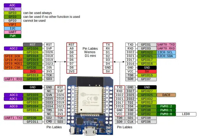
I have it soldered to a Wemos D1 Mini ESP32 board and is reporting data that I can integrate into HA. This is the board:
I’m using this software to get the sensor’s data: GitHub - rain931215/ESPHome-LD2410: ESPHome LD2410 mmWave Radar Sensor Custom Component
Note that I have tried others but the problem is the same, so it’s not a problem with the software.
Connections
Sensor       Board
VCC          3V3
GND          GND
TX           RX (GPIO21)
RX           TX (GPIO17)
OUT          GPIO16 (It is soldered to that pin but I think it's unused by the software)
Here is the YAML config:
uart:
  id: uart1
  tx_pin: GPIO17
  rx_pin: GPIO21
  parity: NONE
  baud_rate: 256000
  stop_bits: 1
  debug:
    direction: BOTH
    dummy_receiver: false
    after:
      delimiter: [0xF8,0xF7,0xF6,0xF5]
The sensor configuration is as described in the project’s config: ESPHome-LD2410/ld2410.yaml at c71e43a39dc851c0b651816739cbbbfb41beeaab · rain931215/ESPHome-LD2410 · GitHub
The problem
So the problem is that this sensor exposes 3 binary states:
- Has Still target
- Has Moving target
- Has target
But there is always one ON. See this GIF as explanation. For this test I’m not even in the same room as the sensor.

It looks like one is the opposite of the other. It never reports all of them as OFF. If the first one is ON, the other will be OFF and vice-versa.
Thoughts
I think the problem must be either one of:
- The sensor is broken
- Soldering the
OUTpin of the sensor is making it act
I have been going through the code and saw where it is getting the values. Here: ESPHome-LD2410/ld2410_uart.h at c71e43a39dc851c0b651816739cbbbfb41beeaab · rain931215/ESPHome-LD2410 · GitHub
#define CHECK_BIT(var, pos) (((var) >> (pos)) & 1)

/*
  Target states: 9th byte
  0x00 = No target
  0x01 = Moving targets
  0x02 = Still targets
  0x03 = Moving+Still targets
*/
char stateByte = buffer[8];

hasTarget->publish_state(stateByte != 0x00);
hasMovingTarget->publish_state(CHECK_BIT(stateByte, 0));
hasStillTarget->publish_state(CHECK_BIT(stateByte, 1));
Is it possible that somehow the bits sent by the sensor are off?
I have to mention that I tested this sensor with another ESP32 board a few weeks ago and it was working properly. So if the sensor is broken it must have been me who broke it.
Thanks for your time, if you can point me to any resource or similar issues I would appreciate it. I’m at a loss.
 Will come back next week and try your suggestions!
 That screenshot is very old and showed the raw value, but I like to keep it up to give you an idea of the entities and how they appear in Home Assistant.
