[HELP] ESPHome mmWave sensor acting weirdly

Hi all,

I have a problem with a sensor acting weirdly and not reporting data correctly.

Scenario

It’s a Hi Link sensor, the LD2410C mmWave presence. This is the sensor:

image

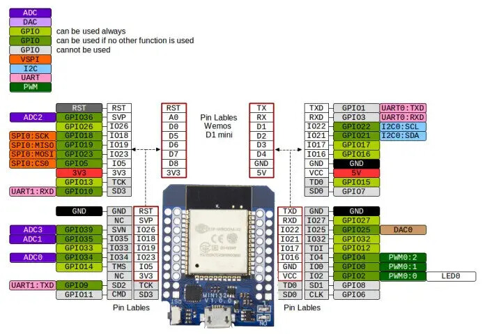
I have it soldered to a Wemos D1 Mini ESP32 board and is reporting data that I can integrate into HA. This is the board:

I’m using this software to get the sensor’s data: GitHub - rain931215/ESPHome-LD2410: ESPHome LD2410 mmWave Radar Sensor Custom Component
Note that I have tried others but the problem is the same, so it’s not a problem with the software.

Connections

Sensor       Board
VCC          3V3
GND          GND
TX           RX (GPIO21)
RX           TX (GPIO17)
OUT          GPIO16 (It is soldered to that pin but I think it's unused by the software)

Here is the YAML config:

uart:
  id: uart1
  tx_pin: GPIO17
  rx_pin: GPIO21
  parity: NONE
  baud_rate: 256000
  stop_bits: 1
  debug:
    direction: BOTH
    dummy_receiver: false
    after:
      delimiter: [0xF8,0xF7,0xF6,0xF5]

The sensor configuration is as described in the project’s config: ESPHome-LD2410/ld2410.yaml at c71e43a39dc851c0b651816739cbbbfb41beeaab · rain931215/ESPHome-LD2410 · GitHub

The problem

So the problem is that this sensor exposes 3 binary states:

  1. Has Still target
  2. Has Moving target
  3. Has target

But there is always one ON. See this GIF as explanation. For this test I’m not even in the same room as the sensor.

screen-capture-1

It looks like one is the opposite of the other. It never reports all of them as OFF. If the first one is ON, the other will be OFF and vice-versa.

Thoughts

I think the problem must be either one of:

  1. The sensor is broken
  2. Soldering the OUT pin of the sensor is making it act

I have been going through the code and saw where it is getting the values. Here: ESPHome-LD2410/ld2410_uart.h at c71e43a39dc851c0b651816739cbbbfb41beeaab · rain931215/ESPHome-LD2410 · GitHub

#define CHECK_BIT(var, pos) (((var) >> (pos)) & 1)

/*
  Target states: 9th byte
  0x00 = No target
  0x01 = Moving targets
  0x02 = Still targets
  0x03 = Moving+Still targets
*/
char stateByte = buffer[8];

hasTarget->publish_state(stateByte != 0x00);
hasMovingTarget->publish_state(CHECK_BIT(stateByte, 0));
hasStillTarget->publish_state(CHECK_BIT(stateByte, 1));

Is it possible that somehow the bits sent by the sensor are off?

I have to mention that I tested this sensor with another ESP32 board a few weeks ago and it was working properly. So if the sensor is broken it must have been me who broke it.

Thanks for your time, if you can point me to any resource or similar issues I would appreciate it. I’m at a loss.
1 Like

I not using the same sensor but a very similar one LD2410 the original one not the “c” version. And really have no idea if this will help or not.

My Uart is configured as below.

uart:
  id: uart_bus
  tx_pin:
    number: GPIO1
  rx_pin: 
    number: GPIO3
  baud_rate: 256000
  parity: NONE
  stop_bits: 1

the first time I set it up on different pins and it did not work. I can only suggest move it to the RX and TX pins.

The config i use came for here

Mine has been working for a few months now, but did take some setting up, to get reliable readings from it.

Hi,
I put together some config on git that you can test out: LoopOnCode · GitHub

It will be used for this: Unity Sensor – LoopOn

If your sensor is using the same protocol as the LD2410 (without the c) then it should work.

Ps: remove the additional sensors from the config.

I know you are using this with an ESP32 device, but have you tried the device using the HI-Link integration?

At least just to see if it’s working ok. I just ordered some and will test the integration when they arrive.

This is likely a software issue.

The official integration, and most of the github adaptations, only allow you to set the number of gates (the maximum distance, where each ‘gate’ is 1m firther from the sensor) or no settings at all.

Most people have resorted to connecting the phone app to do the config.

However, there is a repo that exposes all the gates together with still AND moving energy thresholds which are remotely configurable. Aha! I found it. GitHub - kippesikgithub/esp_motion_mmwave: LD2410 mmwave Motion detection in ESPHome for Home Assistant . Can be combined with temperature, humidity and lux sensor

This exposes all the same settings that exist in the bluetooth android/ios app. You must set each sensitivity for each distance (gate) manually and on a per-room basis to achieve best results. If you want reliable presence (actual mmwave benefits) then this is the way. Nope. He changed his code. Now it’s just a couple parameters. Lame.

My method is to just put the sensor in its final resting place, load up this code on the esp, and then, using known distances and in a different room (because mmwave will penetrate many surfaces) I will watch what type of motion and what distance is observed with nothing there, and then tweak the sensor.

Finally, just ignore the sensor and keep track of when and where you are. Does the output look accurate? Cool, you’re done. It’s not a fast process, but nothing will truly replicate your individual sensor location settings quite like the actual location itself.

I had problems with LD2410 (Not the C model) and D1 Mini because the 5V level was too low for the sensor. With D1 Mini the VCC level was something like 4,6V

Are you really feeding 3,3V for the VCC. I think the C model also wants to have 5-12V for VCC

Thank you guys for your responses.

I’ve been out of town for the last month and couldn’t play with ESP32 :frowning: Will come back next week and try your suggestions!

Did you try the suggestions? Am curiuous.

I have it working and see the same. But in my opinion it is logical. If there is something moving , “moving target” is ON ,and when you are sitting still “Still Target” is ON (and Moving target is OFF). Presence is on is both instances for the timeout period set in the ESPHOME yml file for this sensor. I have it set to 30 seconds.

This problem occurs when the ESP32 firmware is uploaded with the LD2410C connected to it. The sensor was fine, working perfectly for weeks, and after I modified something (anything) on ESPHome and upload the new firmware, after that one of the Still and Moving entity is allways Detected, and 0% energy and 0cm for the Still entity. I have no ideea why yet, I’m trying to sort it out, and also a way to repair the LD2410C modules…

2 Likes

Dude I just saw this and it’s amazing! I’ve been busy and not putting too much attention into HA lately and I missed your comment and the chance to buy the product.

Are you going to make more units?

SOOOOO I managed to sort it out. Kudos to @Arh, @ryny24 and @deadwood83 for pointing me in the right direction.

The sensor is now working properly and it was indeed a sensor’s software issue.
The problem? The detect thresholds

On @Arh’s comment about using the TX and RX, I am not using the hardware UART pins, but custom ones, so indeed this cause a problem as per ESPHome’s docs:

Use of hardware UART pins is highly recommended, in order to support the out-of-the-box 256000 baud rate of the LD2410 sensor.

I did try using the ESPHome’s component but still had the same issues, and I didn’t want to use the hardware UART pins, so I went back to the original repo.

I ended up using the HiLink Android app, connecting through Bluetooth to the sensor and changing the configuration variables following the values described in the ESPHome’s ld2410 component: LD2410 Sensor — ESPHome

Gate Default Move threshold Default Still threshold
0 50 0
1 50 0
2 40 40
3 40 40
4 40 40
5 40 40
6 30 15
7 30 15
8 30 15

It was a process since the app is in Chinese and had to screen capture and use Google Lens to translate it, but eventually managed to set up all the values and the sensor is not jumping around anymore. Then it should be fine tuned as @deadwood83 suggested for each position.

Next step is trying both, the repo shared by @deadwood83 and the ESPHome’s ld2410 component this time more in-depth.

Will post updates if I get any more info.
Thank you all guys and let me know if you have any further questions.

Ok I just tried with ESPHome’s component and it works, feel like an idiot. This is the config I used:

uart:
  id: uart_presence
  tx_pin: YOUR_RX_PIN
  rx_pin: YOUR_TX_PIN
  baud_rate: 256000
  parity: NONE
  stop_bits: 1

ld2410:
  timeout: 5s
  max_move_distance : 6m
  max_still_distance: 0.75m

lock:
  - platform: nuki_lock
    name: Nuki Lock
    is_connected: 
      name: "Nuki Connected"
    is_paired: 
      name: "Nuki Paired"      
    battery_level:
      name: "Nuki Battery Level"

sensor:
  - platform: ld2410
    moving_distance:
      name : Moving Distance
    still_distance:
      name: Still Distance
    moving_energy:
      name: Move Energy
    still_energy:
      name: Still Energy
    detection_distance:
      name: Detection Distance

binary_sensor:
  - platform: ld2410
    has_target:
      name: Presence
    has_moving_target:
      name: Moving Target
    has_still_target:
      name: Still Target

So easy. Then for configuring the distances one can use the configuration variables as explained in the docs:

  • gX_move_threshold (Optional, int): Threshold for the Xth gate for motion detection (X => 0 to 8). Above this level for the considered gate (distance), movement detection will be triggered. Defaults to see table below.
  • gX _still_threshold (Optional, int): Threshold for the Xth gate for still detection. (X => 0 to 8). Above this level for the considered gate (distance), still detection will be triggered. Defaults to see table below.

They’re back in stock! Now there’s an option to get a case and stand for the sensor too.

One question, I see in the website the screen capture with the exposed entities, and the temperature is 44.5°C which I guess it’s closer to the board temperature than to the ambient one. It’s because the sensor is too close to the board? Do you think it can be programatically proportionally adjusted to match room temperature?

Already taken care of :slight_smile: That screenshot is very old and showed the raw value, but I like to keep it up to give you an idea of the entities and how they appear in Home Assistant.

The code that is shipped with the Unity sensors applies what you have suggested. It uses readings from the MCU onboard internal temperature and calculates a more accurate room temperature.

I have some posts with more details on it here and here.

Here are some comparison graphs showing the Unity sensor against another off-the-shelf sensor:
UnityTempComparison

Hope that helps!

1 Like

That’s great man, I’m gonna buy one roday and test it.

Just another thing, could you free the .STL for the case? I like the shape but that transparent color…

1 Like

Yes, of course! The STL file will be made available for free. I can’t offer all the colours in the world but the least I can do is allow you to print your own.

One word of caution, the STL file is designed for resin printing with very tight tolerances (manufacturing level tolerances). You may need to tinker with the scaling to get it working for you.

1 Like

“It was a process since the app is in Chinese and had to screen capture and use Google Lens to translate it”

If you change to english the language of android system before starting HLKRadarTool app, it will be in english…

The Unity case is now available here:

1 Like

I made the same mistake. Any luck bringing the sensor back to life?

edit:
I was able to reset the Sensors to their default state with the Android App.

1 Like