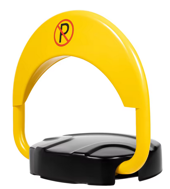
I recently purchased an IP67 Automatic Parking Space Lock Remote Control Parking Barrier Waterproof Private Car Parking Latch Space Lock Yellow (please see the attached photos).
I would like to integrate it with Home Assistant so I can control it through my smart home system.
The barrier operates with an RF remote control that has two buttons:
One button raises the barrier
The other button lowers the barrier
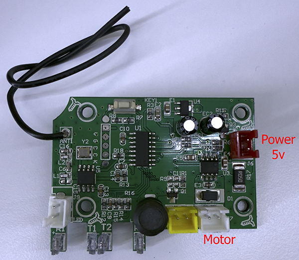
The product runs on 5V DC, and I have attached photos of both the device and its control board.
My challenge is that I am unsure how to connect to or manage the integrated electronic board. I was considering using a Shelly 2PM or an ESP32, but I do not have advanced knowledge of electronics.
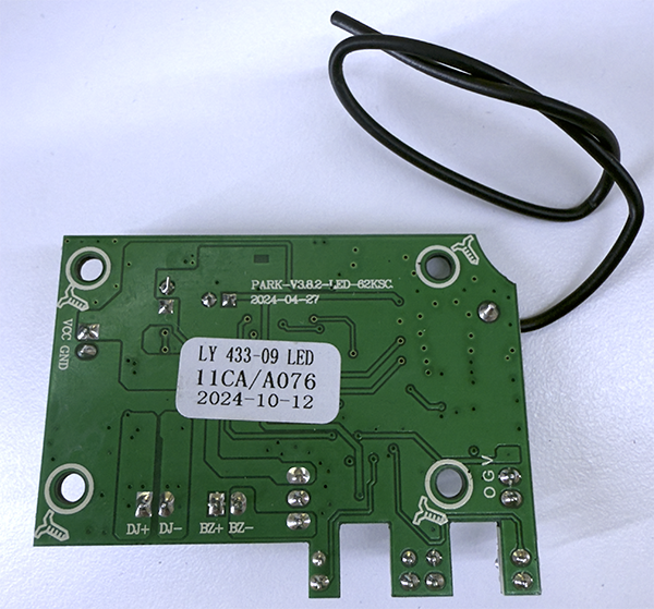
I have searched online for the codes printed on the board, but I have not found any useful information or documentation.
I would appreciate any suggestions regarding:
How to connect a Shelly, ESP32, or another module to control the barrier
Any resources, documentation, or examples of similar integrations
Thank you for your help.
Photos attached: the parking barrier, the front of the control board, and the back of the control board.
Since the device is battery powered, Shelly PM is out of question. Esp/esphome is not really optimized for battery life and transplanting one on the board requires some electronics skills.
Probably easiest option is to copy the RF codes from key fob and send the signal with Esp equipped with 433 transmitter (or some RF-blaster).
I checked again.
The yellow connector is connected to an alarm that emits a sound during the motor’s movement. The other one, the white connector, is not connected to anything, but next to it on the board it says ‘LED’.
T1 and T2, I believe, are optical sensors; in fact, once the board is mounted between two switches, there’s a small wheel.
That’s easier than connecting it to the control board.
But getting 433 modules and cloning the code is the easiest way.
You just need rx and tx modules, rx only to read the code.
Something like these: https://it.aliexpress.com/item/1005003436580019.html