I’m working on an irrigation system using a D1 Mini and 9V latching solenoid valves. The setup uses two relays to reverse the polarity (like an H-bridge) and a 4-way solid-state relay board to trigger individual valves.
Everything is controlled through ESPHome. I can see +9V and -9V correctly at the valve terminals when triggering the switches, but when I connect the actual valve, it doesn’t work properly, and the 9V battery gets hot. It seems like the valve is being powered even when it’s not supposed to.
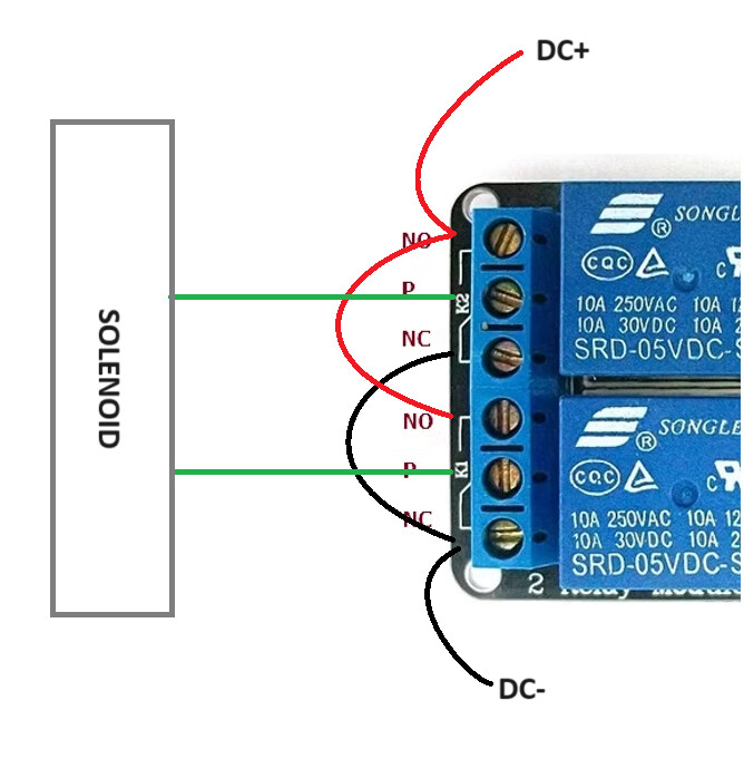
I’ve attached a schematic showing my current setup.
I also tried replacing the solid-state relays with mechanical relays, but the behavior was the same. If I connect the valve directly to the 9V battery (momentarily), it switches as expected.
AC SSR can’t be used for DC load. DC SSR can’t be used with polarity swap.
You can use mechanical relays. Or 2-ch motor driver board.
I’m not able to follow your breadboard “schematic”. Especially with incorrect components.
Even hand drawn diagram would be much better.
Using the same circuit and a mechanical relay, I was able to open and close the latching valve once, but the next 4 attempts failed — the valve didn’t activate at all.
I’m still trying to figure out if the issue is with the relay timing, contact bounce, or maybe battery current limitations. I’m using a 9V battery and a pair of relays configured as an H-bridge to reverse polarity.
Any advice or tested schematics for controlling latching valves with mechanical relays would be really appreciated.
The circuit is more than simple and you don’t need 3 relays for that.
But your description smells like you don’t have the relays input setup correctly.
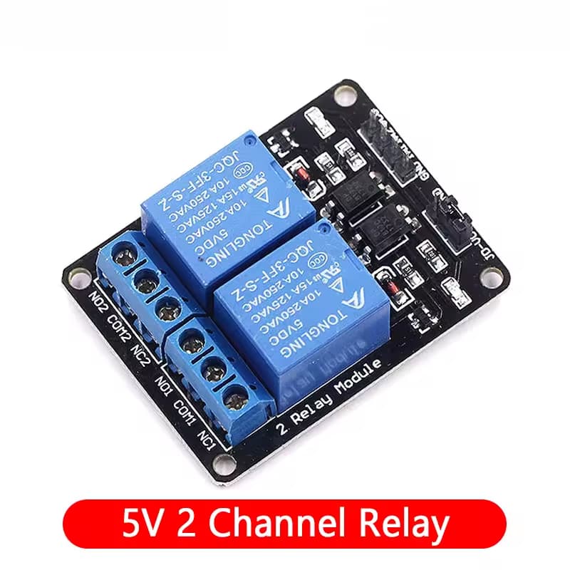
Is the jumper removed? Feel free to post what specific relay module you have and how it’s powered/triggered.
Why not? Two relays are used to switch the voltage provided to the pump from positive to negative in order to close the valve.
This is the relay I’m using attached to the 9v battery: