I was able to solder wires to the board and flash these smart 3 way switches. But I can’t find a configuration anywhere. I can’t find anyone who has even used these before.
The main button on the board is GPIO0. I had to hold the button down to enter flash mode on the ESP.
I guessed at the config and came up with this.
substitutions:
  friendly_name: Shop Light 2
  device_name: shop_light_2
  device_ip: 10.0.10.40

esphome:
  name: $device_name
  platform: ESP8266
  board: esp01_1m
  on_boot:
    priority: -100
    then:
      if:
        condition:
          light.is_on: $device_name
        then:
          - light.turn_off: green_led
          - light.turn_on: red_led
        else:
          - light.turn_off: red_led
          - light.turn_on: green_led

wifi:
  networks:
  - ssid: !secret wifi_ssid
    password: !secret wifi_password
  manual_ip:
    static_ip: $device_ip
    gateway: 10.0.10.1
    subnet: 255.255.255.0
    dns1: 10.0.10.1
  ap:
    ssid: "$friendly_name FBHS"
    password: !secret wifi_password
#  use_address: 10.0.1.31 #use this to change static ip

captive_portal:

logger:

api:

ota:

text_sensor:
  - platform: template
    name: "$friendly_name Uptime"
    id: uptime_human
    icon: mdi:clock-start
  - platform: wifi_info
    ip_address:
      name: "$friendly_name IP Address"
    ssid:
      name: "$friendly_name Connected SSID"
    mac_address:
      name: "$friendly_name Mac Wifi Address"
  - platform: version
    name: "$friendly_name ESPHome version"

sensor:
  - platform: wifi_signal
    name: "$friendly_name WiFi Signal Sensor"
    update_interval: 60s
  - platform: uptime
    internal: true
    name: "$friendly_name Uptime Sensor"
    id: uptime_sensor
    update_interval: 60s
    on_raw_value:
      then:
        - text_sensor.template.publish:
            id: uptime_human
            state: !lambda |-
              int seconds = round(id(uptime_sensor).raw_state);
              int days = seconds / (24 * 3600);
              seconds = seconds % (24 * 3600);
              int hours = seconds / 3600;
              seconds = seconds % 3600;
              int minutes = seconds /  60;
              seconds = seconds % 60;
              return (
                (days ? String(days) + "d " : "") +
                (hours ? String(hours) + "h " : "") +
                (minutes ? String(minutes) + "m " : "") +
                (String(seconds) + "s")
              ).c_str();

output:
  - platform: gpio
    pin: GPIO12
    id: switch_output

  - platform: gpio
    pin:
      number: GPIO4
    id: red_led_output

light:
  - platform: binary
    name: $friendly_name
    id: $device_name
    output: switch_output
    on_turn_on:
      - light.turn_on: red_led
      - light.turn_off: green_led
    on_turn_off:
      - light.turn_off: red_led
      - light.turn_on: green_led

  - platform: status_led
    id: green_led
    internal: True
    pin:
      number: GPIO13
      inverted: True

  - platform: binary
    id: red_led
    output: red_led_output
    internal: True

switch:
  - platform: restart
    name: "$friendly_name Restart"

binary_sensor:
  - platform: gpio
    pin:
      number: GPIO00
    id: ${device_name}_button
    name: $friendly_name Button
    on_press:
      - light.toggle: $device_name
    internal: True
It kinda works…
So the issue I am having, If I use the KS-602F to toggle the light. It works, and it reports to home assistant.
If I use the remote switch (dumb). The light toggles, but it doesn’t report to home assistant. nor do the led’s toggle, and the relay doesn’t click.
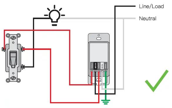
I have HOT coming into the box where the smart switch is. then I have a 4 wire headed out (hot, neutral, traveler, ground). The remote switch is just a 4 wire coming in. I’m not too sure how the light fixtures are wired. I tried all kinds of different wiring configurations.
Now that I took these pictures it looks like the relay is at least a double relay, but I’m lost on the config.
anyone have any insight?
Thanks.
EDIT: ok, today I took the fixture out and traced all the wires. I’m 100% it is wired properly. here is the diagram.

which is the same as how treatlife installs. I have 3 of these treatlife switches working fine. they just program differently.


