Hi-Fi Upgrade for Home Assistant Voice PE!
 Audio Comparison / Sample

Features
- 2x5W speakers
- >= 3x output volume
- Massive increase in audio quality
- One input cable (USB-C power) - everything fits inside the housing
- Reuses stock rubber feet
- Open-source 3D design files
License
This project and its associated files are licensed under CC BY-SA 4.0. You may remix this project, but you must attribute myself / this post as the original source/author, and you must retain the same license when publishing derivatives.

Parts and Tools List
Total cost of purchased components: USD $40
You will need the following tools and parts:


- A Voice PE unit
 “Gikfun 4Ohm 5W Full Range Audio Speakers”
- 20AWG or 18AWG wire - 2 colors (Red+Black recommended)
- Voice PE Hi-Fi 3D printed parts (1 base and 1 lid)
- Screws/Hardware
a. (Qty:3) M3x10 screws
b. (Qty:8) M4x8 screws
c. (Qty:8) M4n nuts - Wire strippers for small gauge wires
- “DROK 5W+5W Mini Audio Amplifier Board PAM8406”
- “HiLetgo XH-M372 Stereo Audio Isolator”
- (Qty:2) Low profile short 3.5mm-3.5mm right-angle audio cable
a. Example: “Kework 3.5mm Audio Cable, 2-Pack 15cm 1/8” 3.5mm" - Soldering iron (I
 my Pinecil!)
 - Screwdriver (Ratcheting preferred) with these bits:
a. PH2 - Philips #2
b. PH1 - Philips #1
c. H2.5 - Hex / Allen 2.5mm
d. F3 - Flathead size 3 - Solder
- (Qty:2) Jump Wire / “Dupont Wire” Male to Female (Red+Black recommended)
(Not shown, optional: 14. Needle nose pliers)
![]() denotes parts that you probably don’t have on your electronics workbench - the total cost of these is roughly ~$40 USD.
denotes parts that you probably don’t have on your electronics workbench - the total cost of these is roughly ~$40 USD.
A part listed “in quotes and italics” means that you can search for exactly those terms in your favorite rainforest-themed online retailer, and you should find the matching part. I wasn’t sure if these types of links were allowed on the forums so I didn’t risk it. Hopefully I made it really easy to find the parts you need. ![]()
Electronic Diagram
In case you were curious. ![]()

Assembly Steps
Clear your workspace.

Cut four ~13cm wire lengths (2 red and 2 black, or any 2 different colors) and strip ~0.5 - 1cm off each end.
Grab the speakers. Find the contact points on one side. There should be two small metal contacts with holes in them. This is the positive and negative connection for the speaker.
(Note: It does not matter which side is positive and which side is negative, but you must do both speakers the same so that you don’t have your speakers out of phase.)
Twist the end of the wire, pass it up through the hole, and solder the wire in place.

You can test to make sure your solder is solid if you can pick up and dangle the speaker by the wire and shake it gently - the solder joint should support the weight of the speaker.

Put the speakers aside.
Grab your Home Assistant Voice PE unit. Make sure it’s completely unplugged.
Make sure the mute switch is UNMUTED.
![]() BEGIN VOICE PE DISASSEMBLY
BEGIN VOICE PE DISASSEMBLY
If you know how to disassemble a Voice PE unit already, or would prefer to follow the official guide instead, you may do so now. You will only need the black mainboard with the scroll wheel, button, and LED diffuser attached, as well as the rubber feet and four small black screws. Scroll down to “END VOICE PE DISASSEMBLY” when finished. Otherwise… read on.

Remove the rubber feet (they are press-fit, so use a fingernail or a flathead screwdriver to pop them off).
Set the rubber feet aside - you will re-use them.
Remove the 4 Philips screws from the base of the unit. Carefully remove the cover from the unit.

Discard or store away the cover and silver screws - these are no longer needed.
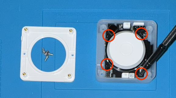
Next, remove the four small black screws keeping the PCB in place.

Carefully pull the mainboard out. Note that the built-in speaker is still attached - carefully pull the connector straight out of the board to disconnect it. (There is no clip holding it in place, it should pop straight off.)

You should now be left with the bottom cover of the unit with the speaker inside, the mainboard with the button/ring still attached, and four black screws.
Discard or store away the bottom cover and speaker - these are no longer needed.
![]() END VOICE PE DISASSEMBLY
END VOICE PE DISASSEMBLY
(Optional: If you also 3D printed a matching replacement button and click wheel - install those now according to the official guide.)

Attach the female end of the jumper cables to the Voice PE mainboard.
![]() VERY IMPORTANT: Plug the wires in EXACTLY as shown below!
VERY IMPORTANT: Plug the wires in EXACTLY as shown below! ![]()

Face the mainboard upright towards you (so the Home Assistant Voice logo is upright).
Connect the female side of the black (or ground color) jumper cable to the top left pin on the LEFT pin group.
Connect the female side of the red (or power color) jumper cable to the top left pin on the RIGHT pin group.
Optional step: Dab some hot glue around where the jumper meets the mainboard to hold it in place.
Plug one of the 3.5mm cables into the mainboard.
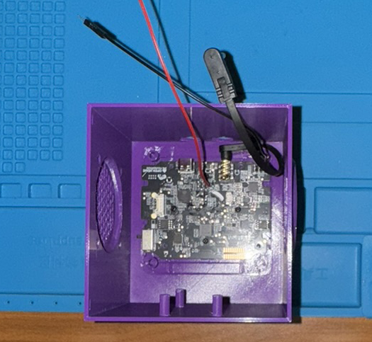
Place the mainboard with the three cables attached into the 3D printed base. It only goes one way. Refer to the picture for correct orientation.
Fasten the four small black screws into the same holes they were previously removed from. You will feel a bit of resistance as the holes underneath are not threaded, so you are “tapping” the screw in. Ensure the screws go all the way down and are snug. Do not overtighten as this can strip the plastic under the screw.

Flip the unit over and ensure that the control ring and button still work, and that the microphone gaskets are visible through the small holes on either side. (Again, it only assembles one way, so if something doesn’t line up, I don’t know what to tell you…)

(Note: Currently there is not a space to mount the isolator module inside the case - this will come in a future iteration. I did not realize a ground loop isolator would be required until after the 3D model was completed and I have not had time to go back and revise it.)
Set aside the unit. Grab the amplifier board.
Prepare the board by loosening/unscrewing (3 turns) all 6 of the terminals on the board. Do not overtighten (over-loosen?).
Take the jumper cables connected to the Voice PE mainboard and connect them to the power side of the amp board (the side with only two terminals). Connect the red wire to the + terminal and the black wire to the - terminal. (The board is labeled.)
Next, grab the ground loop isolator module. Plug the 3.5mm cable from the Voice PE mainboard into one end of the isolator board. Grab the other 3.5mm cable, and connect the other end of the isolator board to the amplifier board’s 3.5mm jack.

When finished, it should look like this.

Next, using the three M3x10 screws, mount the amplifier board to the side of the 3D printed base. See the picture for correct orientation. (When the front of the unit is facing you - the completely flat side - the amplifier should be oriented with the 4 terminals on top, and the volume knob on the right.)

For the top 2 screws, you should be able to screw them in from the top opening, as shown in the picture.

For the bottom screw - there is only one, on the right side of the amp board when facing it towards you - use the hexagonal hole at the back to insert a screwdriver to tighten the screw, as shown above.

Next, grab your speakers.
Place one over the speaker grill. There is a groove, so you should be able to feel when it is set in place.
Take an M4x8 screw and an M4n nut and fasten one of the top corners, with the screwhead on the outside of the unit, driving inwards.

Important Tip: You should not need a socket or pliers to hold the nut! Your thumb/finger should be enough, and once the screw is tight, you can tighten/twist the screwdriver in a “jerking” / quick motion. The nut should grab onto the mounting hole of the speaker after a few jerks, and set into place. You’ll know that it’s set when the force required to tighten it increases significantly. I have assembled 2 of these units now with no socket/pliers/wrench to hold the nuts! It is all about the technique. ![]()
These screws/nuts should be fairly tight (near the limit of a hand tool), but not overly so.


To get the bottom screws, after you get the top ones in place, you can hold the unit sideways, and balance the nut on your finger. Press the nut up against the hole and get the screw started.
You can also try to hold the nut in place using needle nose pliers. The hole near the amplifier board’s volume knob is the only one that gave me a bit of trouble. Persistence is key - you can do it! ![]()

After securing one speaker, secure the other one in the same manner.

Once completed, your setup should look like this.

Next, connect the speakers to their respective terminals on the amplifier board.

The board is labeled and visible looking down from the back side of the board.

Wire the speakers in a cross pattern - the terminals are on the opposite side to where the speakers are. So in the picture above, the left speaker is wired to the terminals on the right (opposite) side to where the speaker is.
The speakers are wired backwards on purpose! The ground loop isolator board reverses the L/R audio channels, therefore it’s necessary to connect the “right” speaker to the left input of the amp board, and vice versa.

Time to test it!
Plug in the Voice PE and wait for the LED lights to illuminate.
Turn on the amplifier by rotating the black knob until it clicks. Increase the volume (continue rotating the knob) until it won’t rotate any longer (100%), and then rotate it back 1/4 of a turn (~80%). This ensures that you can set the Voice PE’s volume to 100% without distorting the audio. (100% on Voice PE and 100% on the amp can cause audio distortions.)
Play some music with something like Music Assistant and make sure it sounds good! (Note - the bass might be lacking a bit - the sound quality increases dramatically after you close the bottom cover. Acoustic resonance and all that. ![]() )
)

If you’re satisfied with everything, pop the bottom lid on (note the small tabs line up with small grooves in the side of the housing). It’s a rectangle, so it only goes on one way. It should click into place.
Install the rubber feet by gently pressing and twisting them into position - they should fit snugly and be identical to the original Voice PE, as the holes were modeled off of the base of the stock unit.
![]() That’s it! You did it! Enjoy high fidelity audio from your Voice PE unit.
That’s it! You did it! Enjoy high fidelity audio from your Voice PE unit. ![]()
FAQ
- The microphone doesn’t work / it’s muted!
- Open the cover, reach in and flip the mute switch. You may need to use a small screwdriver. You may have accidentally flipped it during assembly. This is the mute switch in the unmuted position:
- Open the cover, reach in and flip the mute switch. You may need to use a small screwdriver. You may have accidentally flipped it during assembly. This is the mute switch in the unmuted position:
- I can’t access the mute switch?
- Not in the current design, no. Personally, given the open source and local nature of Voice PE, and the fact that it also has software mute capability via HA, I’m not really worried about the hardware mute switch. But if you are, feel free to modify the 3D printed design to accommodate a mute switch of some sort.

- Not in the current design, no. Personally, given the open source and local nature of Voice PE, and the fact that it also has software mute capability via HA, I’m not really worried about the hardware mute switch. But if you are, feel free to modify the 3D printed design to accommodate a mute switch of some sort.
- Can the Voice PE mainboard really drive speakers this large?
- Yes, while the speakers are rated at 2x5W (10W at 5V is 2 amps), I measured the power difference when audio was playing vs. when it wasn’t, and it only draws an additional ~0.3A, which is within spec for the GPIO pins of the mainboard. (See power meter image below - left half is no music, right half is music.)
- Yes, while the speakers are rated at 2x5W (10W at 5V is 2 amps), I measured the power difference when audio was playing vs. when it wasn’t, and it only draws an additional ~0.3A, which is within spec for the GPIO pins of the mainboard. (See power meter image below - left half is no music, right half is music.)
- There’s no place to mount the ground loop isolator? It’s just dangling in there?
- Yeah, sorry. The ground loop isolator was a last-minute addition, and I wasn’t sure if I was going to use the 3.5mm version or the bare version (that you have to solder yourself). This was easier. V2 of the 3D printed housing will have a space to mount this board.
- Why are there two hexagonal holes on the back?
- For two reasons. First, it improves airflow/resonance for the speakers. Second, if you can’t find right-angle low-profile 3.5mm cables, you can take a regular 3.5mm cable and plug it in using the hole, then U-turn the cable back through the same hole. It will protrude from the back a bit, but that’s okay!
- Your acoustic chamber isn’t very good / could be optimized to increase audio quality.
- You’re right, I’m not an audio engineer. I wanted the unit to be relatively small and easy to 3D print (no supports!) and assemble. But if you think you can improve the acoustics by adding different air channels / ports, feel free to remix the design!
- You’re right, I’m not an audio engineer.
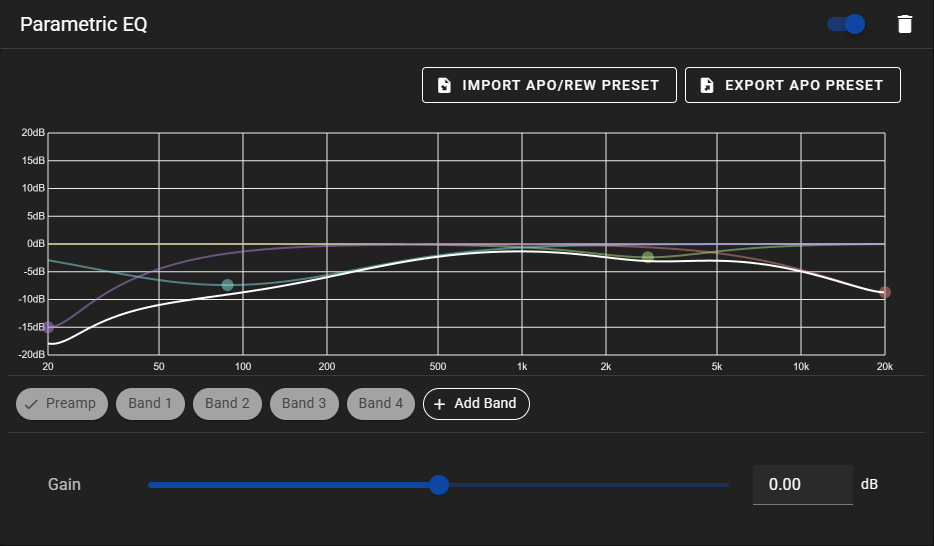
- Can I EQ the sound?
- Not with hardware, no. But Music Assistant now supports a software parametric EQ - you could try that!
- I don’t like these speakers / I want to use different 2x5W speakers.
- There are other speaker deisgns/configurations out there (for example, search “MakerHawk Double Cavity 5 Watt Speaker”), and modifications to the housing could support other speakers in the future, yes.
- This still isn’t as good / loud as <insert tech giant voice assistant device here>!
- Yeah, it’s not. But I couldn’t find a more powerful readily-available amplifier board that was that tiny, and even if I did, I’m not sure the Voice PE mainboard would be able to drive anything more than 10W total anyway.
- This is fantastic! Can I support you with a donation / subscription?
- First off, thank you! However, I am financially stable, and I do this for fun in my spare time as a hobby. I would encourage you to make a charitable donation with the money instead.
- First off, thank you! However, I am financially stable, and I do this for fun in my spare time as a hobby.


Comments / Suggestions / Feedback are welcome!
And if you make one yourself, I would love to see it! Please post a picture!