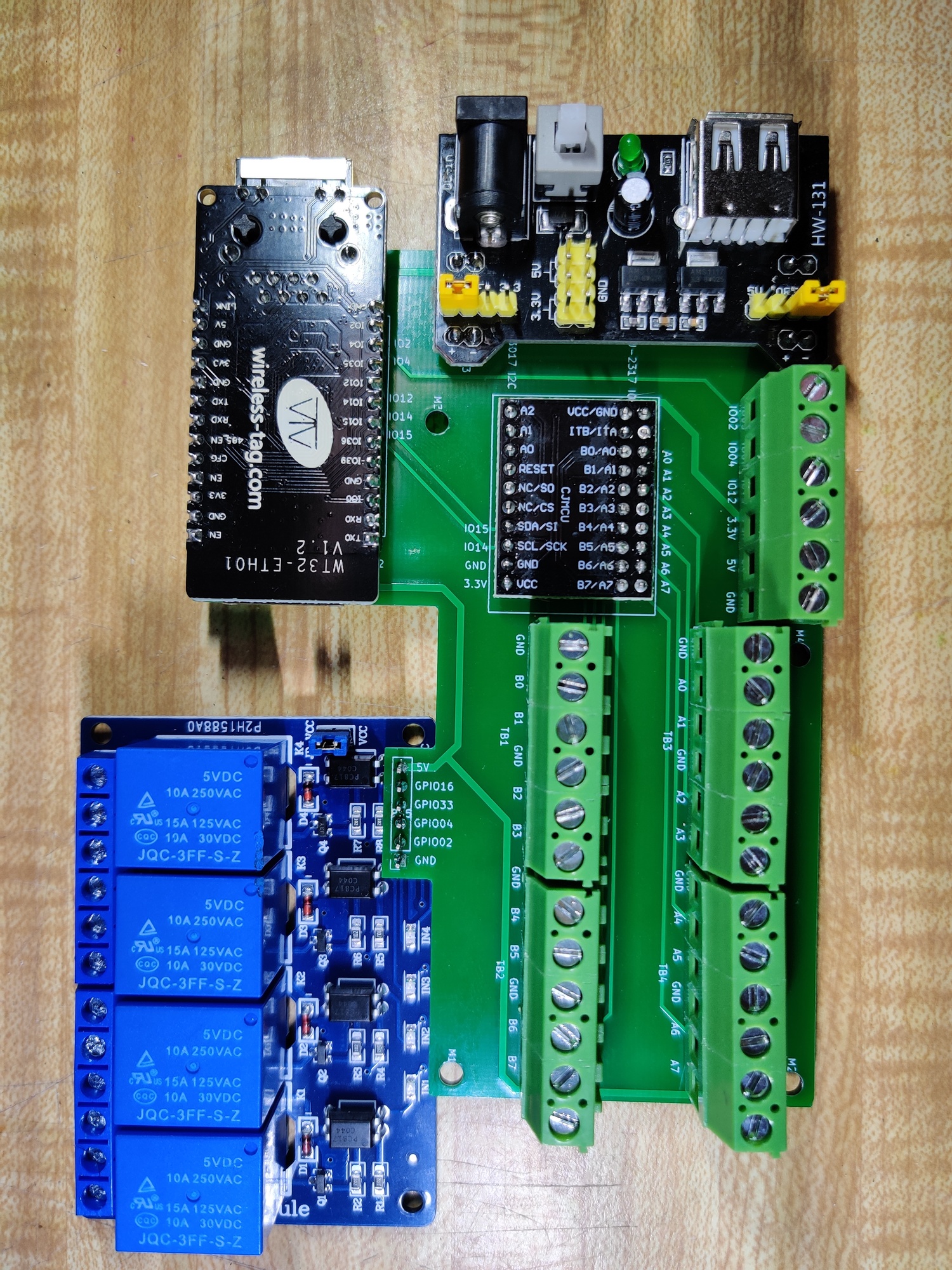
For the past few months I have been working on a PCB board which assembles some popular modules into one security panel. I am sharing this project and hope you guys like it.
Some of the components/modules used in this projects are:
wireless-tag WT32-ETH01 Ethernet module
MCP23017 IO expansion module
generic 4 channel relay
generic 3.3V 5V Power Supply Module
Terminal connectors
In the end, the product is an ESP32 security panel with 4 channel relay, 19 channel GPIO, bluetooth, wifi, ethernet, screw terminals. Compared to WiFi, ethernet connection is much more secure and reliable. It also cut’s the network delay.
The datasheet says the internal pullup is 100K. That’s super weak and really only good at a board level.
But more important is the lack of isolation. Datasheet specifies that the GPIO pins are only capable of handling 4KV of electrostatic discharge. If you connect long wires directly to the GPIO pins you run the risk of frying the chip (or causing false readings, which could range from inconvenient to disastrous in an alarm application) if there is a spike on the wire. Spikes can be caused by strong radio transmissions, lightening, a fluorescent light nearby striking, A/C compressor starting, etc.
Without isolation it also means tying the grounds together which can introduce ground loops (especially with long wires and separate power supplies).
All commercial alarm panels use a lot of buffering, electrostatic discharge protection devices (ranging from snubbers to MOVs to spark gaps) and sometimes optical isolation.
Thank you so much for your detailed explanation! This is very helpful. I use a single PC power unit backed by an UPS so the group loop is not an issue for myself. But I do notice that lightening can induce some strange behaviors to the system. I have no EE background, will see how much I can improve when I get time. Really appreciate your help.