UPDATED - Sept 9, 2023 - added control for valve actuator & moved to larger enclosure
Hi all,
For anybody in posterity interested in integrating a solar pool heater control to HomeAssistant via ESPHome, this is how I did it…
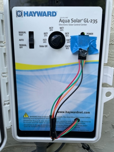
My solar pool heating system is controlled by a Hayward GL-235 (rebranded from Goldline).
I’m using:
- 1 x ESP32 WROOM
- 2 x INA219 DC Current sensors (one of them with the A0 pins connected to give me a different I2C address)
- 1 x BH1750 lux sensor
- 1 x Hi-Link HLK-PM03 AC to DC convertor
- 1 x Adafruit Non-Latching Mini Relay FeatherWing (only needed for pool valve actuator)
- 1 x 240v-24v transformer (only needed for pool valve actuator)
The concept:
There are 2 x 10K thermistors connected to the motherboard - one measures the temperature of the pool water, one measures the roof temperature. I’ve co-wired the 2 INA219s to the existing wires on the connectors to measure the voltage. I then calculate resistance & temperature from that.
I’m using the BH1750 lux sensor to measure the light level of the ‘heating’ led which tells me the system is pushing water to the roof. A text_sensor is then set to “Heating” or “Not Heating” based on the lux measured.
I pull 240V from the pool controller incoming power and use the HLK-PM03 to convert that to 3.3v
I also added a relay to be able to control a valve actuator that opens / closes my waterfall at certain intervals.
In a Fritzing diagram, it looks like this:

Note on the diagram: the model for the AC to DC is the 5V one - couldn’t find a 3.3V version 
Here’s the config I use for this all:
text_sensor:
  - platform: template
    name: "Pool Heating Status"
    id: esphome_pool_heating_status
    icon: mdi:heat-wave

# This switch is only needed for pool valve actuator!
switch:
  - platform: gpio
    name: "Waterfall Switch"
    id: waterfall_switch
    pin:
      number: 26
i2c:
  sda: 32
  scl: 33
  scan: true

sensor:
  - platform: ina219
    address: 0x40
    bus_voltage:
      name: "Pool Sensor Voltage"
      id: pool_voltage

  - platform: ina219
    address: 0x41
    bus_voltage:
      name: "Roof Sensor Voltage"
      id: roof_voltage

  - platform: resistance
    sensor: pool_voltage
    configuration: DOWNSTREAM
    resistor: 10kOhm
    name: "Pool Sensor Resistance"
    id: pool_resistance
    reference_voltage: 5V

  - platform: resistance
    sensor: roof_voltage
    configuration: DOWNSTREAM
    resistor: 10kOhm
    name: "Roof Sensor Resistance"
    id: roof_resistance
    reference_voltage: 5V

  - platform: ntc
    sensor: pool_resistance
    calibration:
      - 10.0kOhm -> 25°C
      - 32.648kOhm -> 0°C
      - 15.711kOhm -> 15°C
    name: "Pool Temperature"
    id: pool_temperature

  - platform: ntc
    sensor: roof_resistance
    calibration:
      - 10.0kOhm -> 25°C
      - 32.648kOhm -> 0°C
      - 15.711kOhm -> 15°C
    name: "Roof Temperature"
    id: roof_temperature

  - platform: bh1750
    name: "Pool LED Level"
    address: 0x23
    update_interval: 60s
    id: pool_led_level

  - platform: bh1750
    name: Pool Heating Status Sensor
    id: pool_heating_status_sensor
    update_interval: 60s
    on_raw_value:
      then:
        - text_sensor.template.publish:
            id: esphome_pool_heating_status
            state: !lambda |-
              if (x >= 50) {
                return "Heating";
              } else {
                return "Not Heating";
              }
And here’s what the finished board looks like mounted in a waterproof enclosure next to the controller:

And the light sensor on the controller panel:
And finally, the results in Home Assistant:


Hopefully somebody will find this useful.
 ) but seems that when I created this post I used a very early version of my config which, as you rightly mention, is faulty - it is indeed not pulling the current but rather the voltage