I recently bought the INSPIRE EMINGO ceiling lamp from Leroy Merlin.
It comes with a proprietary RF remote but the remote is unreliable (button presses often don’t register), and the lamp frequently loses its brightness and color temperature settings.
After seeing a teardown of the similar Leroy Merlin GDANSK lamp here, I decided to fully replace the RF controller with an ESP32 running ESPHome.
This has given me reliable control, proper CCT/brightness mixing, and a native Home Assistant integration.
Below is a complete guide for converting the INSPIRE EMINGO to ESPHome.
Hardware info
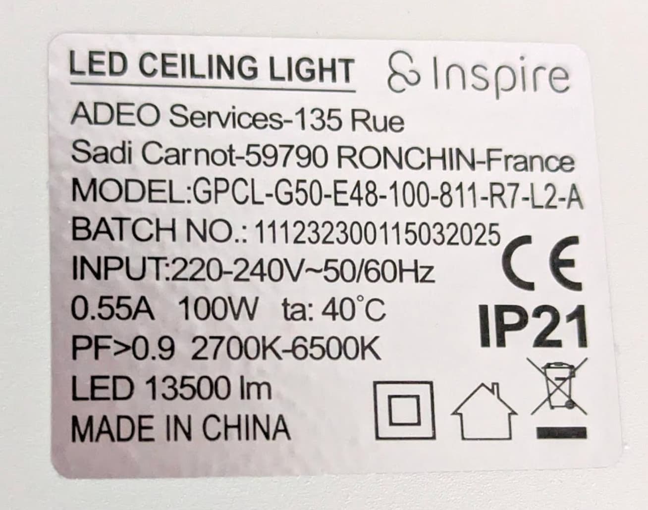
- Lamp Model: INSPIRE EMINGO
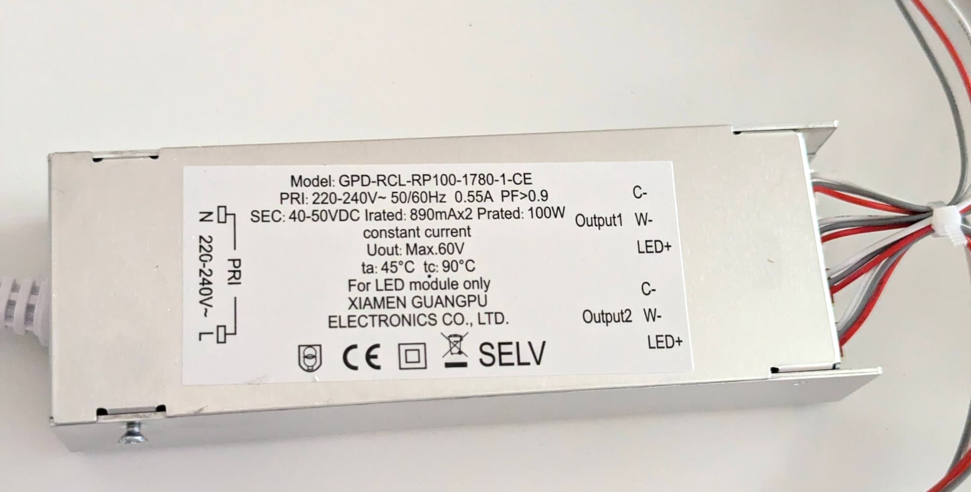
- LED Driver Model: GPD-RCL-RP100-1780-1-CE (technical data sheet)
- Driver Specs
- Output: 60 V DC, 100 W
- Luminous flux: 13500 lm
- Two LED strips with a shared brightness setting but optionally independent color temperature
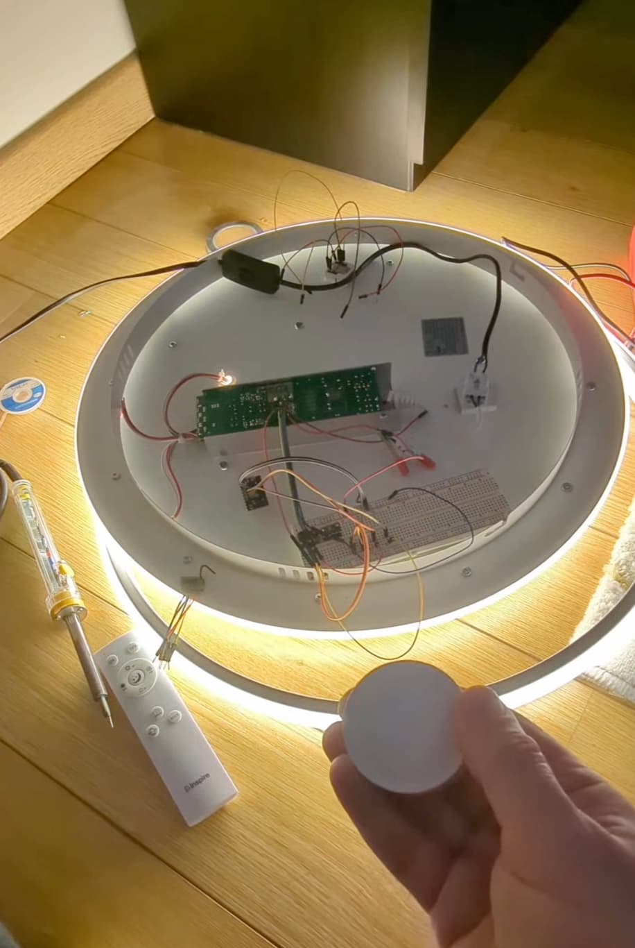
Some pictures

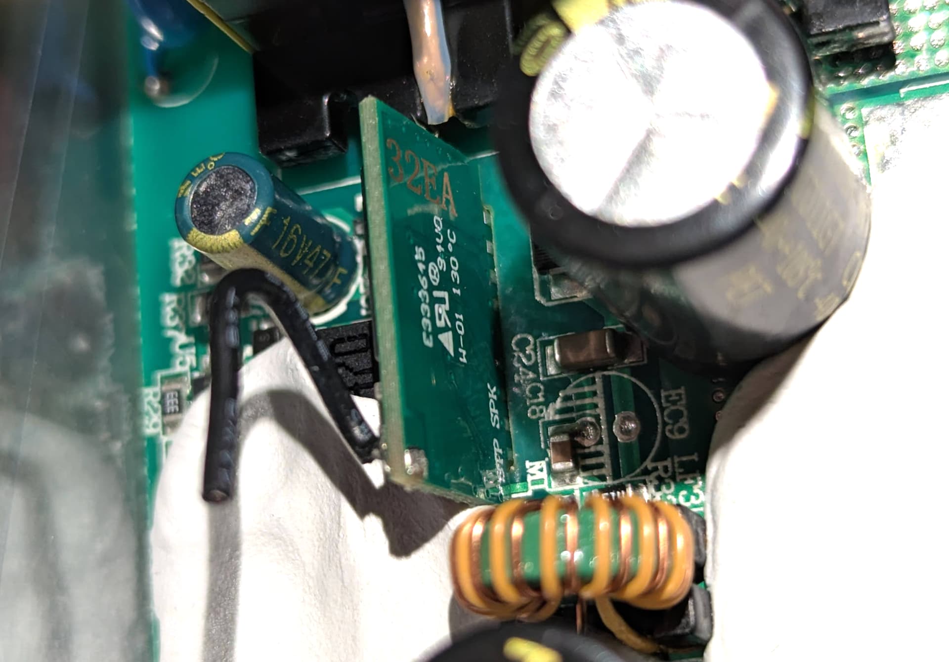
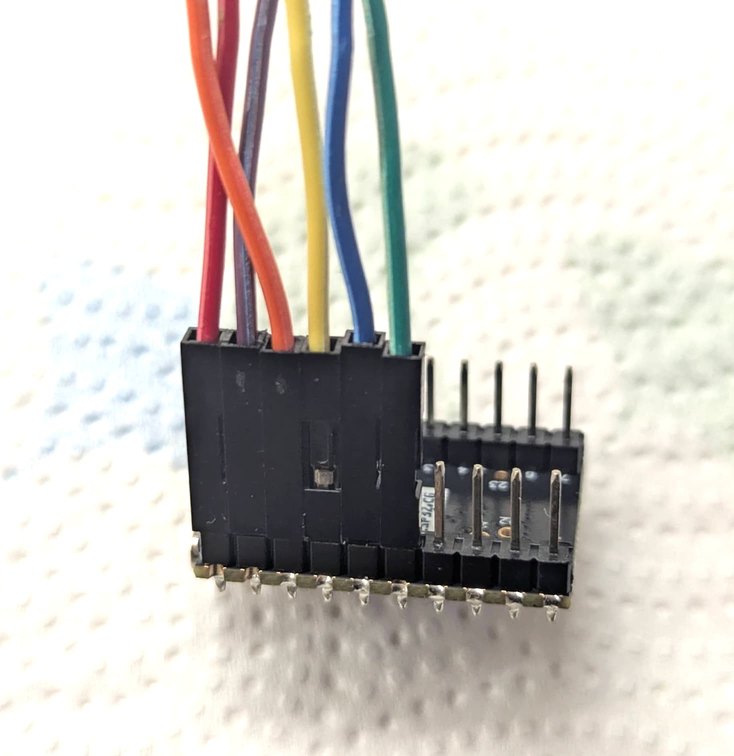
RF module from the top:
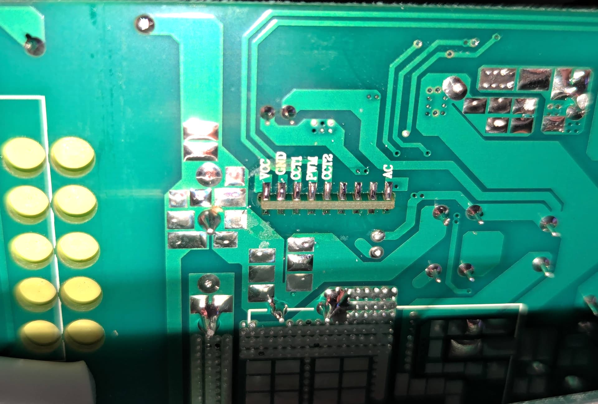
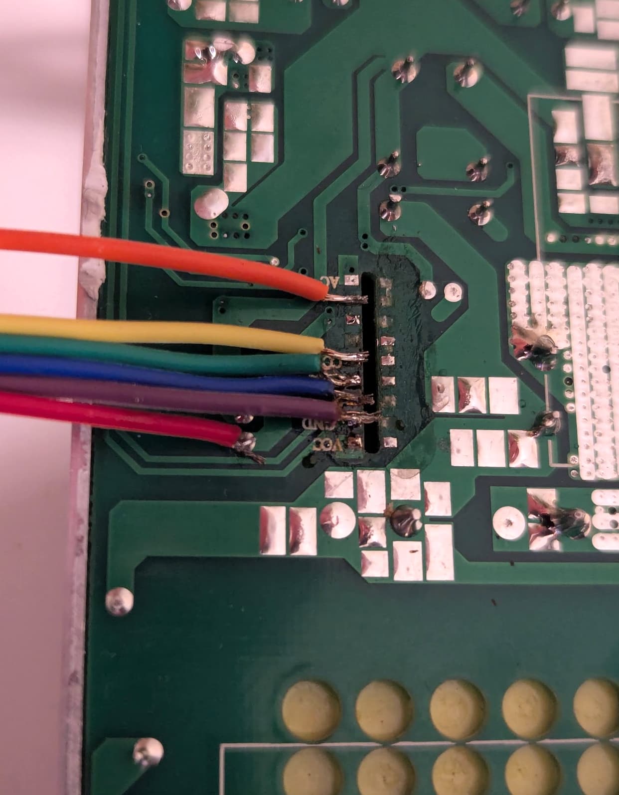
RF module from the bottom:
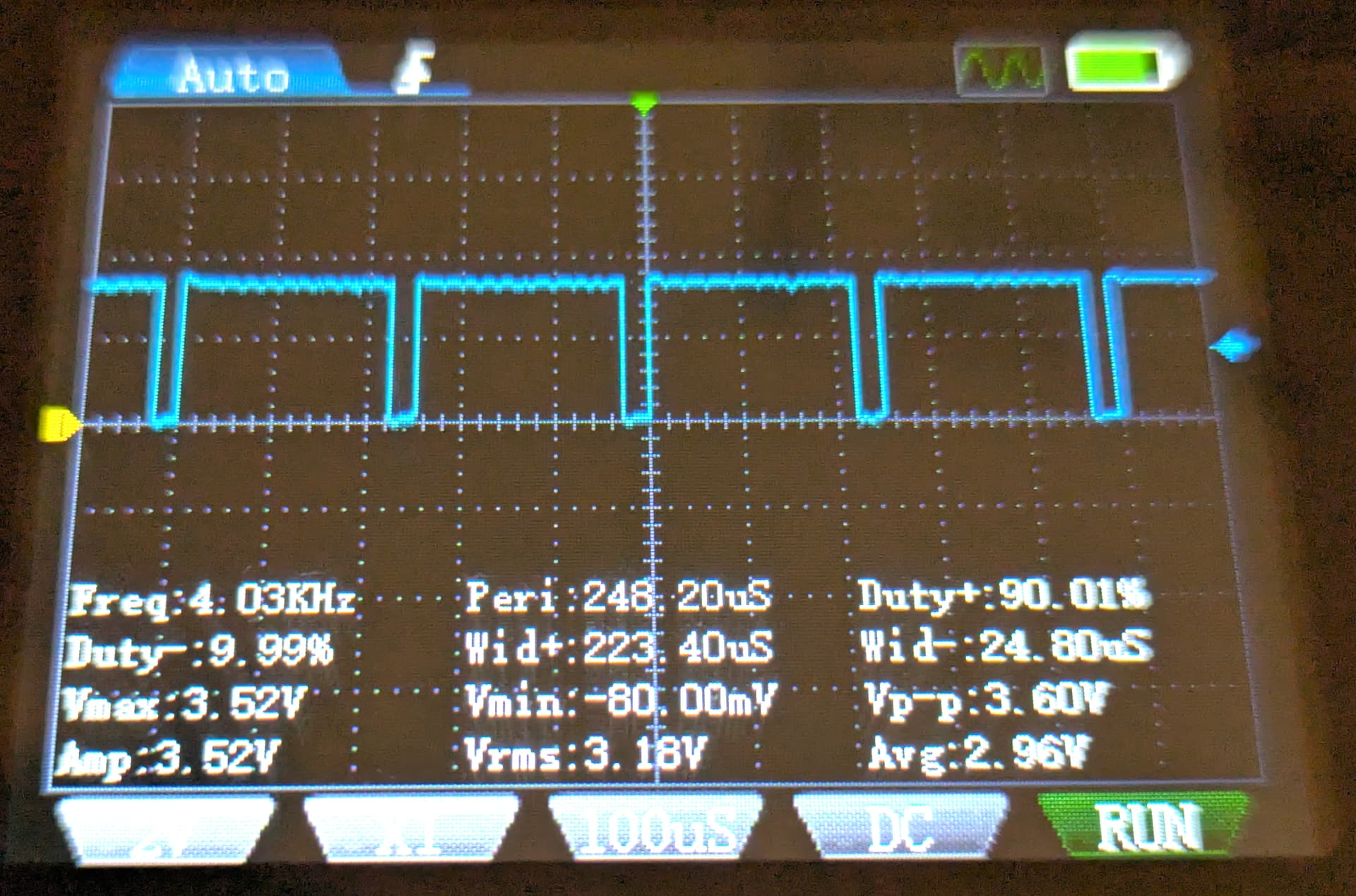
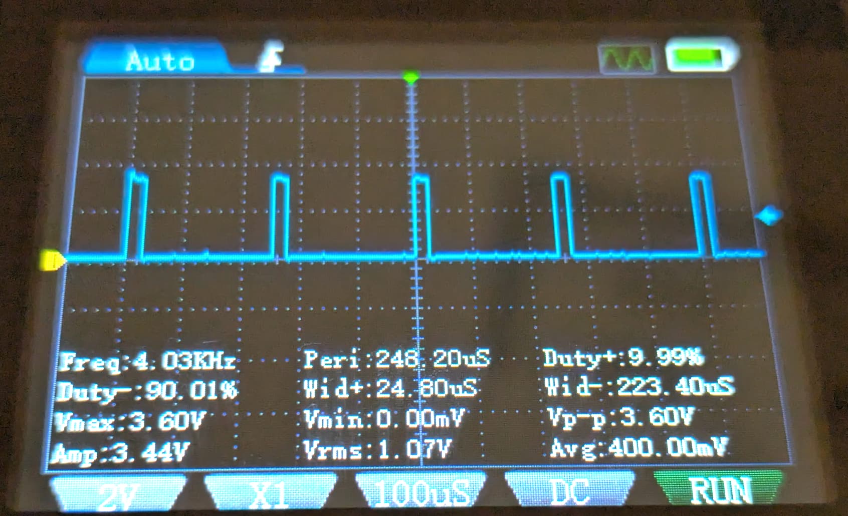
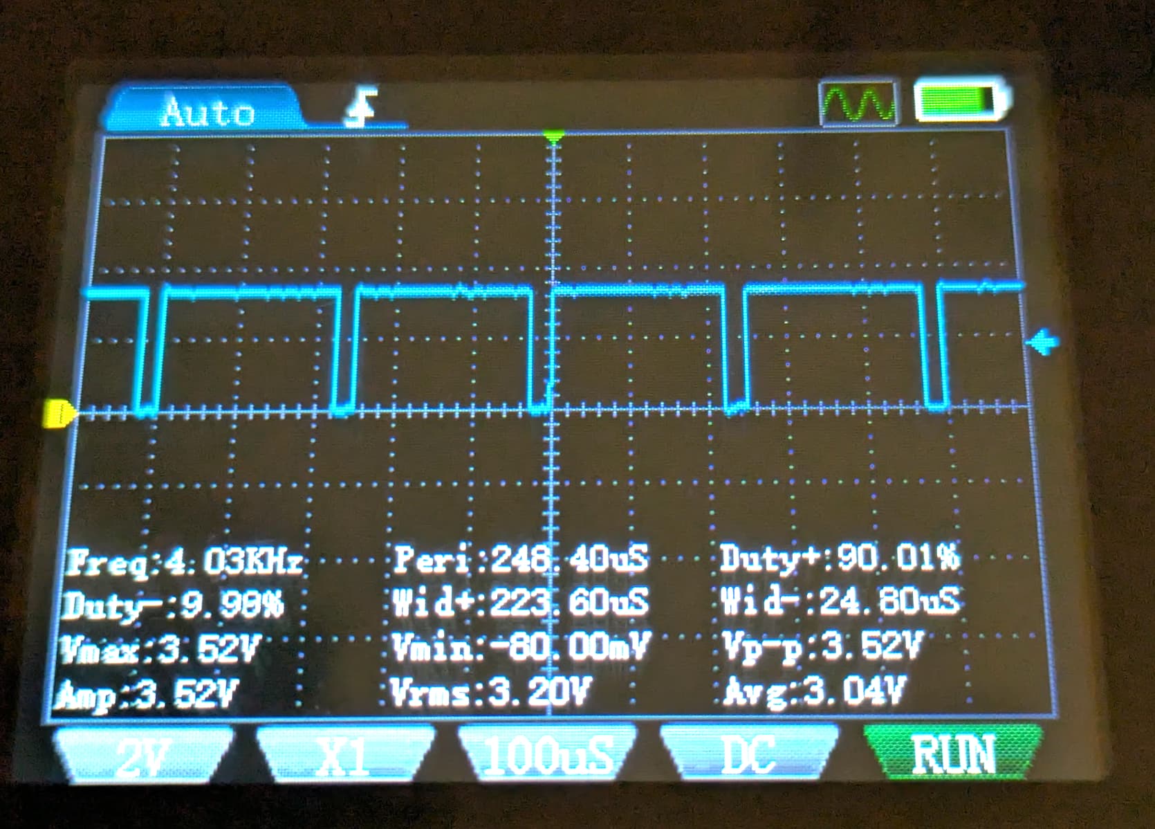
Oscilloscope captures:
PWM Pin - 90% duty for brightness at 90%
PWM Pin - 10% duty for brightness at 10%
CCT1 or CCT2 Pin - 90% duty for almost fully cold white
Pinout and How the Lamp Works
In practice, the RF module only makes use of 6 out of 9 pins. It communicates with the LED driver using three PWM signals:
| Pin | Function | Notes |
|---|---|---|
| VCC (3.3V) | Powers the RF board | Not enough current for an ESP32 |
| GND | Ground | — |
| PWM | Brightness | 4 kHz PWM, 0–100% |
| CCT1 | Warm/Cold mixing (Strip 1) | 4 kHz PWM, inverted |
| CCT2 | Warm/Cold mixing (Strip 2) | Same as CCT1 |
| — | Unused | — |
| — | Unused | — |
| SFP (or SP/EN) | Must be held at 3.3V | Enable signal |
| AC | Unused | — |
Behavior
- PWM = overall brightness
- CCT1/CCT2 = color temperature
- 0% → Warm
- 100% → Cold
- SFP must stay high or the driver disables output.
- VCC cannot power an ESP32 (too little current).
- A nearby 5.3V pad can power the ESP32 reliably.
Here is the connection diagram with the pins that will be reused:

Hardware Modifications
The 3.3v VCC pin looked like the most obvious pin to power the ESP32 but turns out it doesn’t provide enough current so the ESP32 was not even booting properly.
Fortunately, I was able to find a 5.3v pin just a bit away from the other pins. It provides 5.3v with enough current to reliably power the ESP32.
To start, I unsoldered the original RF module. Then I soldered some jumper wires. These soldering pins are really small and close to one another. I’m not too experienced in soldering so my soldering job looks quite bad but it works.
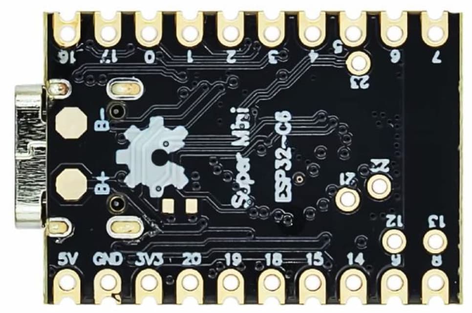
Then I connected the jumper wires to an ESP32-C6 Super Mini. Here’s a wiring table.
| ESP32-C6 Pin | LED Driver Pad | Purpose |
|---|---|---|
| 5V | 5.3V pad | Power input |
| GND | GND | Ground |
| 3.3V | SFP | Keep driver enabled |
| GPIO 18 | PWM | Brightness |
| GPIO 19 | CCT1 | Color temp (strip 1) |
| GPIO 20 | CCT2 | Color temp (strip 2) |
ESPHome Configuration
Below is the configuration I used. It implements:
- 4 kHz hardware PWM (matches the driver’s original PWM frequency)
- Paired CCT outputs (both strips always in sync)
- Automatic brightness + CCT restoration after reboot
- Optional Thread support
esphome:
  name: ceiling-lamp
  friendly_name: Ceiling lamp

esp32:
  board: esp32-c6-devkitc-1
  variant: esp32c6
  flash_size: 4MB
  framework:
    type: esp-idf
    version: latest

preferences:
  # Writes color temp and brightness settings to flash every X seconds so we can
  # recover the same state after the device reboots.
  # Careful, might lead to quicker flash wearout.
  flash_write_interval: 20s

api:
  encryption:
    key: "YOUR_ENCRYPTION_KEY"

logger:
  level: INFO

ota:
  - platform: esphome

wifi:
  ssid: !secret wifi_ssid
  password: !secret wifi_password

## OpenThread config. Alternative to WiFi - START ##
#network:
#  enable_ipv6: true
#openthread:
#  # OpenThread TLV value from the Thread information in Home Assistant
#  tlv: YOUR_TLV_VALUE
#  force_dataset: true
## OpenThread config - END ##

output:
  - platform: ledc
    id: hw_brightness
    pin: GPIO18
    frequency: 4000

  - platform: ledc
    id: hw_cct_strip_1
    pin: GPIO19
    frequency: 4000
    inverted: true

  - platform: ledc
    id: hw_cct_strip_2
    pin: GPIO20
    frequency: 4000
    inverted: true

  - platform: template
    id: temp_brightness
    type: float
    write_action:
      - lambda: |-
          id(hw_brightness).set_level(state);

  # Single output value for both color temperature pins to keep both strips in sync
  - platform: template
    id: temp_cct
    type: float
    write_action:
      - lambda: |-
          id(hw_cct_strip_1).set_level(state);
          id(hw_cct_strip_2).set_level(state);

light:
  - platform: color_temperature
    name: "Lamp"
    id: lamp

    # These are the outputs that the light system writes to
    brightness: temp_brightness
    color_temperature: temp_cct

    gamma_correct: 1.0

    warm_white_color_temperature: 2700 K
    cold_white_color_temperature: 6500 K

    restore_mode: RESTORE_AND_ON
Home Assistant Integration
Once flashed, the lamp appears in Home Assistant as a native ESPHome light entity:
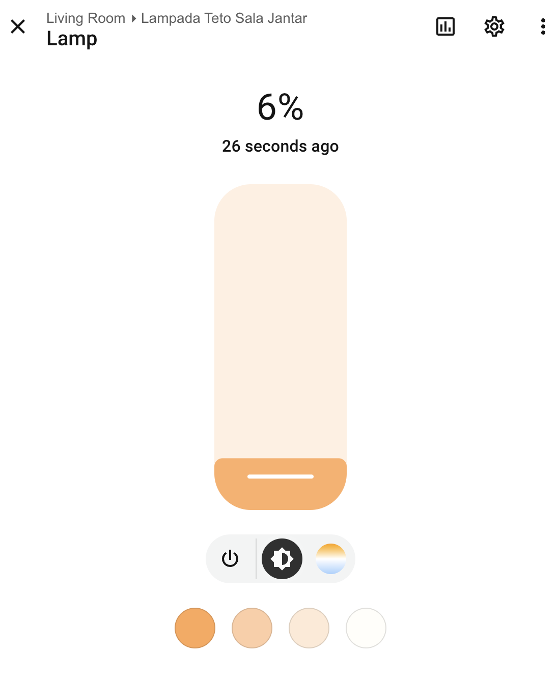
Brightness and color temperature work smoothly and restore after power cycling.
Controlling the Lamp with a Zigbee Knob
I tested the setup using a Tuya Zigbee Smart Knob paired to Home Assistant through Zigbee2MQTT.
Final remarks
Everything works really well. With the Thread configuration I’m able to control the lamp within less than 2-3 seconds after powering it up but that time sometimes increases to 10s+ when the lamp is actually fixed to the ceiling. Maybe an ESP32 with an external antenna would improve reception.
Hope this helps someone else!