I need to read some states from and external existing device (the main unit of a wired alarm) which brings out those states as 12V levels or using some LEDS of which I need to detect if they are lit or not.
I’m using a Wemos D1 Mini ESP32 board, and I’m encountering a lot of problems in reading the remote states. I searched a lot on the internet but I cannot realize what I’m doing wrong.
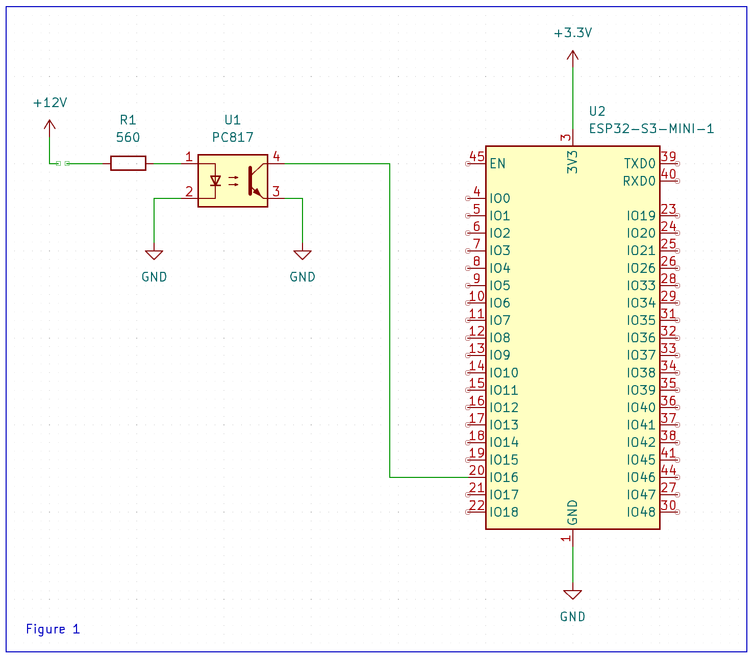
On both figures below the D1 mini board is powered using a 3.3V regulator which shares the GND pin with the remote system.
and it didn’t work: simply nothing happens when connecting +12V to pin 1 of the PC817 or removing it the gpio16 pin value remains stable, so I was not able to detect state change.
After a lot of searching I was able to find a guy who realized something very similar to my needs, so I changed my circuit as in Figure 2 above on the right, using the following code:
here I added the switch/led in order to have a local state for the input without the need to look at HomeAssistant screen.
At first I tried the figure 2 circuit without the 1MOhm resistor, and the behaviour got crazy: if I don’t connect to 12V the pin 1 of the PC817 the onboard led blinks randomly, so the state showed in HomeAssistant.
After adding the 1MOhm resistor it got stable, but again I was not able to detect any state change.
First one will work if your wiring match the circuit (and your optocoupler is not damaged).
You don’t have logger on your yaml, so how you expect to see if it’s triggering?
Connect your optopcoupler to your microcontroller using a pullup resistor like the example below I pulled from my I/O boards :
You can also use the internal pullup but I prefer physical pullups since it means I don’t have to remember to configure something in software (then troubleshoot why it doesn’t work when I forgot).
Ground the transistor side of your optocoupler to the microcontroller ground. Ground the LED side of the optocoupler to the alarm circuit ground.
First one will work if your wiring match the circuit (and your optocoupler is not damaged).
I hope my optocoupler is not damaged, I’ll check or change it.
I’m sure my wiring match the cicuit.
You don’t have logger on your yaml, so how you expect to see if it’s triggering?
I have logging (I removed it from yaml for simplicity) anyway I expect to see the GPIO going up or down from HomeAssistant , or to see the led going lit or dim as in the second yaml
You should also check in documentation is that pin have pullup capatibility, or just put external one, lets say 1k, between io pin and 3V3.
Best regards,
Without the pullup resistor, either internal or external, the pin is probably always pulled low. Or perhaps floating if the optocoupler is turned off. Depends on impedance.
Add the pullup resistor and it should start working. Out of habit I always use 4.7K pullups. But any value greater than 1K to about 50K will work.
Ok, just a message to thank you all and to resume my issue.
First, it happened that trying and trying again and wiring and rewiring my circuit I ended up breaking my PC817 optocoupler … and obviously I didn’t notice immediately.
Now I use a socket in order to be able to check it and to replace it easily.
So I rewired my circuit to be powered from micro-USB and I replaced the optocoupler, and now… it works!
Schematic identical to figure 1 in my first post, except for the power supply which now comes from micro-USB, and using internal pullups.
I’m planning to insert a pulldown resistor between GND and pin 1 of the optocoupler, not to have a potentially floating input… but in any case I’m already happy like this!