As a relative novice, I struggled to work out how to install the Sonoff ZBMINI-L2 switch in my garage with (I think) fairly standard UK 2-way light switch wiring, no neutral.
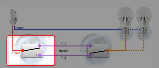
The Sonoff diagram for my scenario is this one:
The following is my noddy expanded version showing how this was applied in my setup:
Thanks for this. I’ve come to install one but I have a 2 gang switch instead of 2 separate switches
At top of backbox is 2 sets of cables, one on medfly I believe is upstairs landing light and one on right is the hall light which I am trying to add this module to
Top of switch;
Earth → connected to back box
COM → right hand red cable
L2 → left hand red cable
L1 → left hand blue cable
Bottom:
L2; blank
L1; black from right hand cable
COM - yellow from left hand cable
Can you advise me what I need to connect where so I can validate my internal thinking?
I’ve tried to set this up myself as well, but am failing.
Can I just clarify - you originally had TWO wires in each of L1/L2 on S2 ? One of each was moved to the Lin/Lout on the Sonoff - these presumably would have been brown and blue with a brown sleeve ?
I don’t seem to have that setup - I have neutral wires in my switch box, and the permanent live is on the COM of S2 (equivalent).
I can get it wired up so the relay controls the light, but not so the switch controls the relay, plus the light is always on regardless of the position of S1, if S2 (or the relay) is on.
I don’t think I can use S1/S2 on the Sonoff unless the switching circuit is separated from the power, which I don’t think it is - one of L1/L2 on my S1 is always live.
When I wire Lin / Lout and measure voltage at the Sonoff S1/S2 I get 240V and 200V respectively. Not sure if that means anything, but as I’ve blown up one relay in the past wiring power across S1/2 I’m keen to avoid doing it again !
There’s going to be some trial and error at some point I think. I am presuming I should be putting the relay at the switch that has the permanent Live wire.
@Lazy_pete - If you have Neutral in your wiring then you may need another device - The ZBMINI L2 is designed for a setup with no neutral. Perhaps a re-think about which device to use?
Hi,
you are saying you moved the Red cables from Switch L1 and L2 to Sonoff L in and L out. Where do then the grey and Black cables come from which are now in S2 L1 & L2? Are These New cables?
Just wanted to pop here and say thanks for this! I’ve been holding off doing this for a while with the components on my desk. Finally bit the bullet at this little drawing really helped
Okay understood you moved the Red from S2 L1 and L2. But in S2 L1 and L2 are the grey and Black ones which stay unchanged. So where is the solution? Sorry, I simply dont get that haha
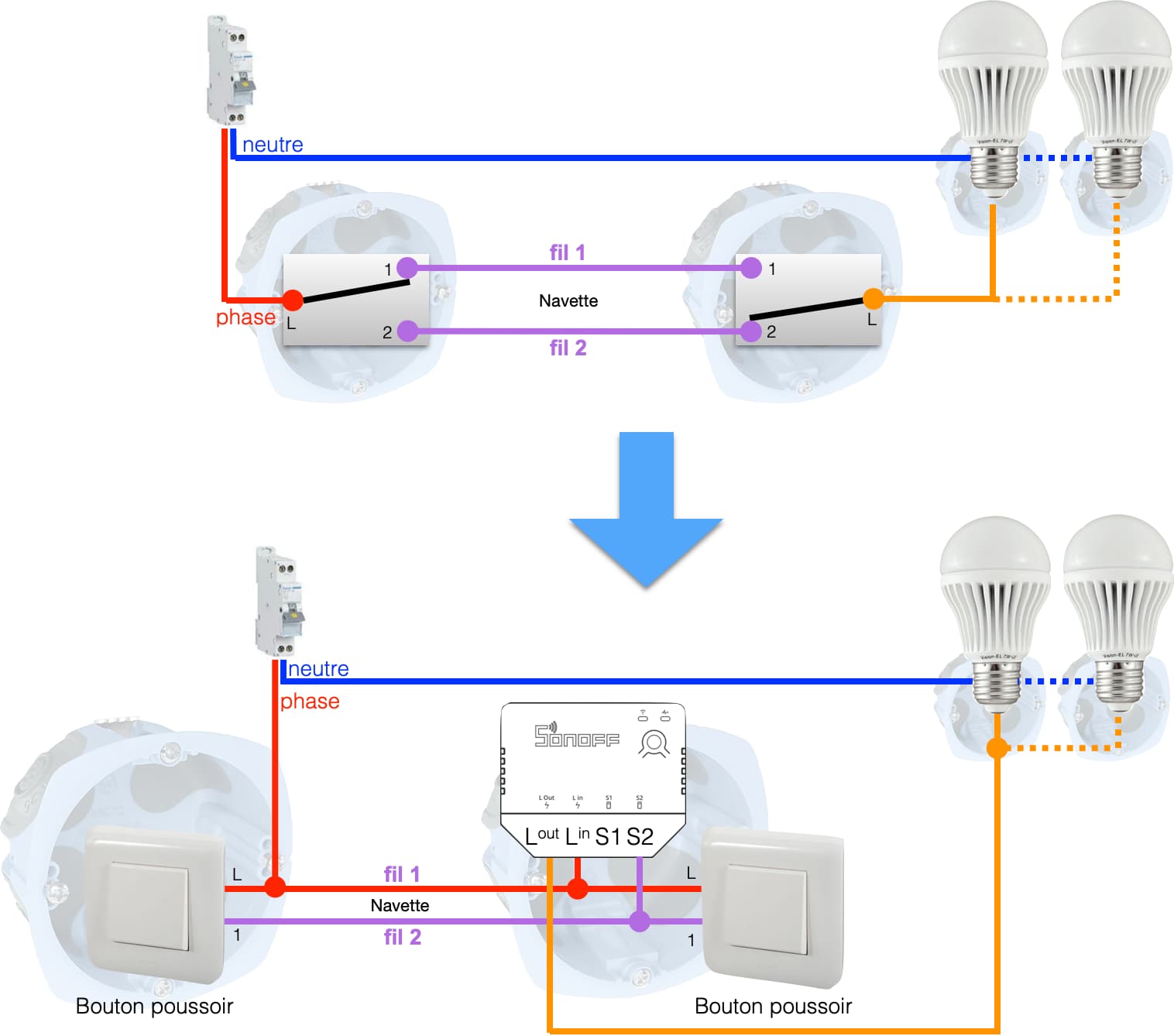
If anyone is searching for a more simple solution, without the need to add a new wire, you can use the following diagram.
It “just” requires that you swap your regular switches with pushbuttons switches.
Phase : Line
Neutre : Neutral
Fil : Wire Source.