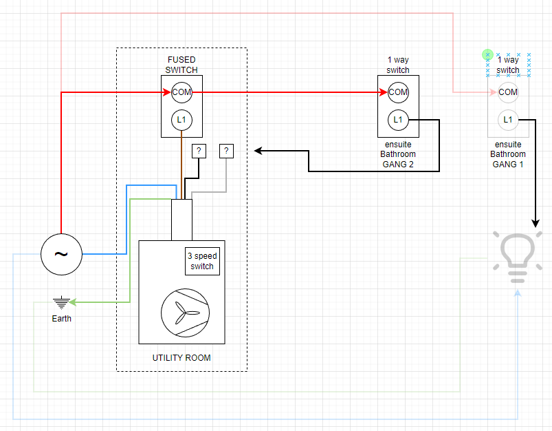
Finally, a schematic that makes sense. It does raise some design questions, but that’s not your issue.
For example, how do they control three speeds with a single pole switch?
Questions for you:
What is the “3 pole isolator”? Is it integral to the unit? Is it a circuit breaker or a switch? Is it normally on? (“Isolator” is not that common a term for residential wiring here.)
I know that double-pole wall switches exist, but I’ve never seen one in a typical home installation.
And, again, you haven’t said what you want to do from Home Assistant?
I have no idea what the 3 pole isolator does, just took the diagram from the installation guide of the MrBox.
All I want to do in home assistant is to switch on the ensuite switch based on the humidity of the main and ensuite bathroom using a sonoff sensor and kitchen humidity using the Tado wireless temperature sensor. Sensors are already setup in Home Assistant.
I have already replaced the 2 gang switch on the main bathroom with a dumb one gang switch to control the lights and terminated the MrBox cables.
I now have left a dumb 2 gang switch at the ensuite which controls lights and MrBox, I want to replace it with a dumb 1 gang switch to control the lights and a relay to switch the MrBox solely based on humidity readings.
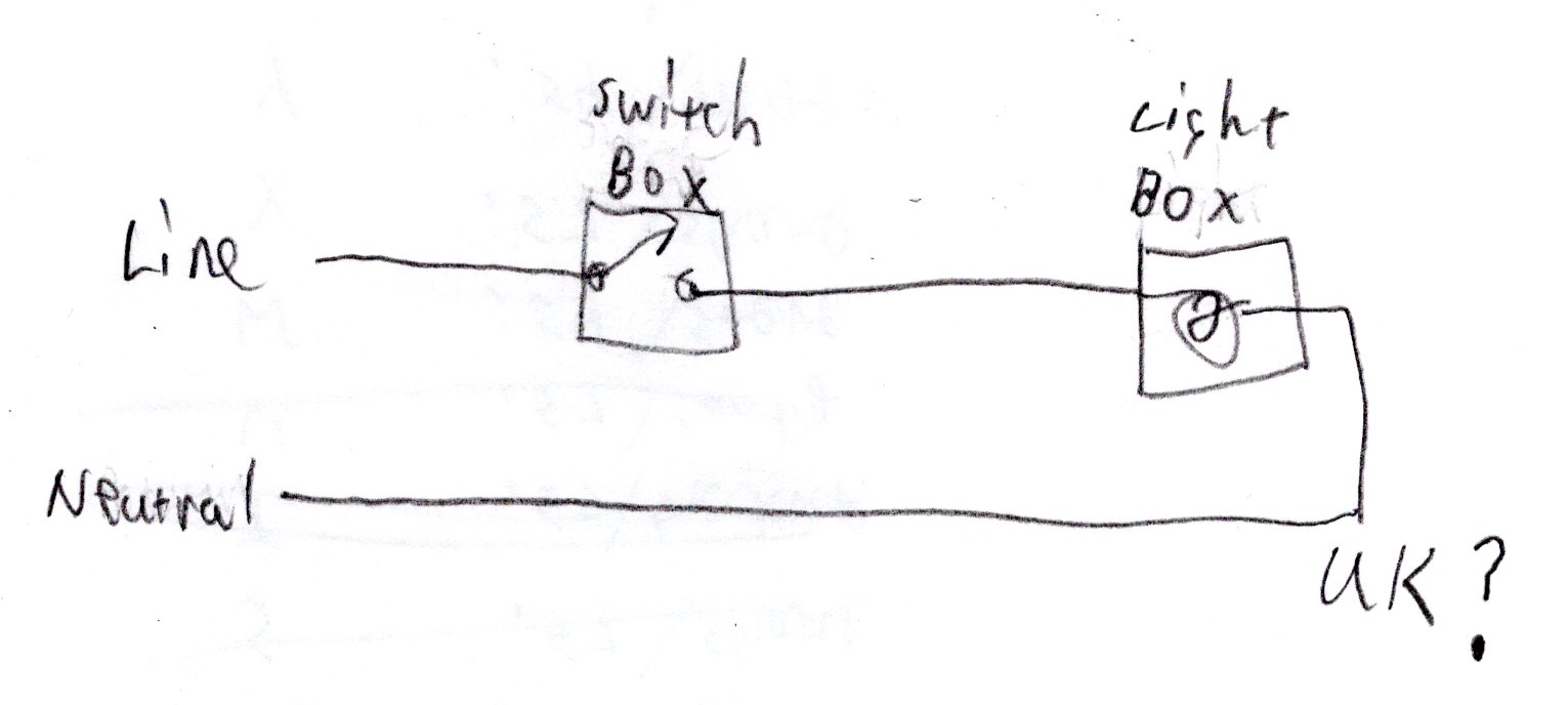
We have determined that the neutrals are not really neutrals and belong to the lights circuit which is separate from the MrBox, therefore I need a Zigbee (or WiFi of only option) 1 gang relay that supports 155w
Then don’t call the wires “neutral”. I think the correct term is “return” or “passthrough”. Maybe someone familiar with UK home wiring can correct me. So are you saying that each switch location only has two wires in the box? (That is so wrong and rarely happens in the U.S.)
What you described as goals for Home Assistant are totally doable. Now, connect a dumb single-gang switch to control the MrBox. Just to test if this is what you want the relay to do. If you verify that this that you want to control the circuit with a relay instead of the 1G dumb switch, then make a drawing of that circuit. From there we may have recommendations for connecting the relay and controlling it from Home Assistant.
Where, specifically, do you want to put the smart relay? I would recommend putting it in or on the MrBox since you know you have a neutral there. Just remove the wires going to the switch and connect the normally-open (N.O.) contacts of the relay where the switch wires formerly went.
I would like to see the patient. Post a photo of the MrBox installation. Does the wiring cable from the MrBox go into a electrical junction box? Take a photo of that as well.
4 is the breaker for the MVHR, 7 is the breaker for Bedroom/Bathroom/Hallway lighting
Now, connect a dumb single-gang switch to control the MrBox. Just to test if this is what you want the relay to do. If you verify that this that you want to control the circuit with a relay instead of the 1G dumb switch, then make a drawing of that circuit.
I already have a 2 gang dumb switch as originally installed, the gang controlling the fan speed just have a COM and L1 wire so ideally I’m thinking to swap the dumb GANG2 with a relay, only downside I have no neutral, but now I’m also thinking that it’s unlikely it has a 155w load? As this switch only control the fan speed? I’m not sure if it’s connected to the Black or Grey cable from the MrBox (but if I put the relay at the ensuite bathroom switch I don’t really care)
I would recommend putting it in or on the MrBox since you know you have a neutral there. Just remove the wires going to the switch and connect the normally-open (N.O.) contacts of the relay where the switch wires formerly went.
I agree it makes a lot of sense what you say, however I’m not sure if the load coming from the ensuite switch is going to the Grey or Black cable? However should be easy to determine by using the switch and check which cable become live.
Putting the relay at the MrBox make sense, I’m vary though to work on the fused switch, it seems easier to just automate the existing dumb switch… IF the load won’t be so high (but again, I believe 100w would be plenty?)
How can I measure the W drawn at the ensuite switch?
First, WHAT DOES THE ENSUITE SWITCH control? Does it turn the MrBox on or off or is it the speed switch? That is still unclear.
I’ll grind you on the semantics. Watts is wrong here. If your switch is drawing watts of power, you have a bad, and dangerous switch. The switch should be between 0-Ohms and infinity. If it’s anything in-between then it is consuming power in the form of heat. What you want to know is how many amps is going through the switch. For this your easiest measurement is with a clamp-on ammeter. If the switch is the speed control, my estimate would be that the switch handles very little current. Probably only enough to energize a relay inside of the MrBox. If the switch is the on/off, then it could be carrying the complete load of the MrBox.
If all you want to do is to replace a normally-open wall switch with a smart relay, just put the normally-open contacts of the relay where the switch wires go. As I said before, if you put the smart relay inside the MrBox, you know there is a neutral wire there.
If you want to put the relay at the switch location, then I can’t help you. I have never seen a receptacle box without a neutral wire, let alone installed a smart switch in one. (I was an electrician in a prior century).
I didn’t say that. I said that MY GUESS is that the fan speed switch PROBABLY operates a relay inside the MrBox. It’s difficult to say without seeing the schematic of the MrBox if the speed control operates a relay. If you get a clamp-on ammeter we could be 99% certain.
The specs of the switch module are puzzling: " * Current rating: 100W LED". A 100-Watt LED would be bright enough to light a Hollywood Studio. But according to Ohms Law, 100W at 230V is less than half an amp. ???
Since the switch says “Click Scolmore CSP041 White 1 Gang Zigbee 100W LED Smart Switch Module” and at such a low power, I have to wonder is there is a relay inside the module. But even a Mosfet could handle more current than half an Amp. If there is no relay inside, connecting it to an AC load would likely smoke the module.
Oh yeah the specs of the switch module are not really well documented… It takes tho 220-240V so should be designed for AC power? The 2 gang I had worked aside from tripping the RCD (as I was mixing lights and MrBox circuits) and died overnight but most likely due to the shorts when hooked to both lights and MrBox
I have got this:
I put the clamp around the L1 cable and flipped the switch for the fan boost (at the ensuite switch where I want to put the smart switch) and I’ve got: 150V~ and 0.015A~ (with the clamp meter set on A~ 2/20)
Since it’s not labeled on any of your schematics, I have no clue what “L1 cable” refers to. If this is the wire labeled “fan-speed” that you want to replace with a relay then 15mA would likely be a relay coil. But is it AC or DC? If the Zigbee LED controller is, as I fear NOT a relay, then it would only work with a DC load. When you get the Zigbee box, post the wiring instructions because I can’t find them on the Internet.
I’ve received the relay… it works with AC (stated in the manual) and it works perfectly with the bathroom lights but if I use the load of the MrBox it gets no power at all… no clue why.
I’ve then ordered a Sonoff and I’ll attempt to hook it up at the MVHR switch in the utility room, I already took it apart and identified the Neutral and the Load going to the Black cable.
Will update this post if the Sonoff works.
It seems my unit was wired in a weird way as the MrBox fan boost should be linked to the lights but in my case they kept the fan speed boost and lights circuits separate.
Is the 3-pole isolator a switch, I assume so since isolators in the US generally means a circuit breaker?
If the “isolator” is open, then no. The relay will do nothing because there is no “line” going to the MrBox brown wire. Without knowing what the Brown, Black and Grey wires go to in the Mr. Box, everything is just a guess. I AM GUESSING that the brown wire is the line into MrBox and that the black and grey wires control a relay inside. If this were mine and absent a schematic, I would need to open MrBox and trace where these wires go. If you have a clamp-on ampmeter, then what is the current on the brown, black and gray wires in normal operations?
I thought you said that you wanted to duplicate the function of the kitchen switch? What are you trying to accomplish wiring it as shown in your lower drawing? Again, what do you want to control from Home Assistant?
Also, the way you have the Sonoff wired, ALL of the neutral current is going through the Somoff.
Wiring it this way is very dangerous. Your relay is bypassing the isolator on both N and whatever the black MrBox wire is. An isolator is for isolating a circuit (duh) and that means completely cutting in off from the power supply. Your wiring defeats this. The Sonoff/whatever will power (part of) the MrBox even when the isolator is turned off. Not only is this completely against code, it can also seriously injure someone who would turn the isolator off for maintenance on the MrBox.
I rewired the brown and blue coming from the MrBox to the relay, so now the relay is not bypassing the isolator, even though is not really crucial in my case as the circuit is already separated from the light circuits.
The three blue cables slewed in brown are the “switch lives” for the 2 bathrooms and the kitchen switch which I will just insulate as I won’t use any physical switch.
The grey cable for fan speed 3 is not utilized, I may consider adding a second relay for that one… but for now happy as it is… off course not exactly “as it is” I’ll cut a bit of plasterboard and add an external box to host the relay safely with no exposed cables.