I keep shorting relays... how to choose the right one?

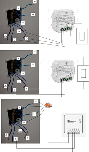
Hello, I’m failing to properly automate my ventilation system and I keep shorting relays. Attached a diagram of what I try to do, I’m trying to put the relay in the Switch 2 which currently is a two gangs controlling the ensuite lights and the ventilation speed.

The ventilation system I have is the MrBox ECO 2 from Nuaire:
LINK:info.nuaire.co.uk/catalogue/MRXBOX-ECO2.pdf

It has a maximum power consumption of 155Watts according to the PDF, however, the label on the product states 152W

I originally got a 2 gang smart click relay:
LINK:www.directelectrical.co.uk/products/Home+Automation/Click+Scolmore+Home+Automation/White+2+Gang+Zigbee+2+x+100W+LED+Smart+Switch+Module%2C+IP20/2497932556

I can now see that they are 100W per output… so that is not ideal, but even before getting there… I blew the first one because I wired it wrongly putting live in one of the switch terminals on the relay (ooops)

Then for the second one I wired it “properly” but… toggling the relay was causing the RCD1 or RCD2 to trip… I believe because the relay has only one Live input, so if I put the MrCOM in the relay, when I switch the lights the RCD1 trip, if I put the L(ights) COM in the relay, the RCD2 trip when switching the lights.

I have then gave up on the idea of retaining the two gangs and tried to use the smart relay only to automate the ventialtion based on humidity, so I’ve removed switch inputs on the relay and just had the MrCOM in the line input and the MrL1 in the output.
I’ve then used a dumb switch for the lights, this worked, I could toggle the ventilation via HomeAssistant without tripping, however, the morning after it the smart relay was completely dead (although was not operated during the night)

I’ve then got a zigbee mini from SONOFF planning to use the Neutrals.
LINK:sonoff.tech/wp-content/uploads/2021/08/%E4%BA%A7%E5%93%81%E5%8F%82%E6%95%B0%E8%A1%A8-ZBMINI-20210811.pdf

This is rated for 2200W so I thought I was golden… I wired all N1, 2, 3, 4 together and used a jumper cable to the Nin of the Sonoff, then used the MrCOM and MrL1 for line input and output…

This tripped bot RCD1 and RCD2… I now undertand that this is because the Neutrals of for the lights only? So the sonoff is dead again.

I then understand that I cannot use a relay that require a Neutral because I cannot “cross” the circuits… I’m ok as said to automate only the MrBox… would it be ok then to get this one:
LINK:www.directelectrical.co.uk/products/Home+Automation/Click+Scolmore+Home+Automation/White+1+Gang+Zigbee+250W+LED+Smart+Switch+Module%2C+IP20/1325174863

I have disconnected the terminals on Switch1 for the MrBox and replaced that switch with one gang for the lights only.

All works without trips with dumb switches on Switch 2

Any help appreciated!

Your “schematic” resolves very little information. What is the box labeled “lights”? What is RCD? How are they wired? How is the Sonoff Mini wired?

The schematic needs to be at this detail before I can make sense of your issue. Show exactly how you wired your circuits.

2 Likes

Thanks for your patience, I’m no electrician for sure, hope I can clarify here.

RCD is:
A residual-current device (RCD), residual-current circuit breaker (RCCB) or ground fault circuit interrupter (GFCI)[a] is an electrical safety device that quickly breaks an electrical circuit with leakage current to ground.

I have 3 RCDs in my panel, one for the whole house and the other 2 for 2 groups of circuits breakers that control the different rooms/appliances.

So the “Lights” box next to RCD2 is a the circuit breaker for the lights in the bedroom and bathrooms
The “MrBox” box next to RCD1 is the circuit breaker for the MrBox ECO 2 ventilation system

My understanding is that I cannot use a 2 gang relay because the RCD1 or RCD2 will detect a leakage (as current from the MrBox circuit will flow to the lights or viceversa) so when I tried to use the relay as two gangs using a dumb switch for the lights every time I tried to switch on the MrBox via Home Assistant the RCD1 and 2 was tripping. (L com is the com cable for the Lights, Mr com is the com cable for MrBox)

I then gave up to the idea of using 2 gangs and wired the MrBox COM and L1 to the relay, that worked but as said in the morning the relay was dead.

I tried the Sonoff one which shorted immediately as I switch on the circuit breaker for MrBox.
I would assume because again the Neutrals are from the Light switches which is separate from the MrBox circuit

My question is basically if the second option with only MrBox on the relay should work if I get a relay that can provide 155W, being the relay I had was rated at 100W I guess that is the reason why it stopped to function overnight.

I am an engineer. Engineers speak in schematics. Not pictures.
The switch modules in your pictures is not the same as the module you described in your first post. There is not enough information in your pictures for me to help you, and engineers don’t read.

This is a picture. For an engineer it means nothing.


Some would take the time to redraw pictures into something readable, but not presenting a real schematic greatly reduces the number of people willing to decipher your pictures.

This i s a schematic.

An engineer can understand the wiring at a glance of a schematic.

A picture of the relay device is OK if it is accompanied with a link to the technical specifications (in a link tag) but what is most significantly missing from your pictures are the rest of the circuit. By the way, all neutral wires are connected together so there is no need to show the routing of every one of them,

I’m still confused with the circuits, but let me try this:

It seems that you have two circuits -

  • One for the MrBox Nuaire ventilation system which is on an RCD (“RCD1”) and breaker (“MrBox”).
  • Two is for the lights to the bathroom/ensuite which are also on an RCD (“RCD2”) and breaker (“Lights”)

You were connecting in a relay module into “switch 2” to control the lights and ventilation system but this was causing RCD’s to drop.

The images provided are a little unclear as to what attaches to what, but I see what must be the control lines for the ventilation unit and lighting circuits, but these are all blue wires, except “Mr COM” which is brown. Are you saying that the lights are switched on the neutral here and not on the live feeds?
Why are the live wires blue, I do not know - very confusing and possibly not to spec?

Looking at the linked relay modules, I notice that the ZigBee module is neutral free and went faulty, but that you were intending on using one of the available “neutrals” with the Sonoff module.

Yes, I think that’s the issue here. An RCD measures the balance between the outgoing current on the live supply and compares it against the returning current on neutral. As you were using a “neutral free” relay unit, the power for this unit is derived from the current within the attached circuits, and you were sharing it across both the ventilation and lights circuit, so this was going to happen as the current’s return path was split between the RCD’s, triggering a fault.

Firstly, you need to work out whether you have a true neutral within that switchbox, and if so which RCD circuit it’s on. You need a proper neutral as the relay module needs to be powered independently and isolated from the switched supply if it’s not controlling the same circuit. These types of relays are commonly called “dry contacts”. The relay modules linked above are not isolated and they appear to be “wet contacts” - ie - the module itself shares current with the outputs. (https://www.electrical4u.com/dry-contacts/)

So, I’d recommend that you start by looking for a true neutral which come off the same supply circuit as the MrBox - if that’s still where you want to power the relay from, otherwise try source a true neutral and matching live from another suitable circuit.
Hopefully this makes sense.

Thanks, I definitely not able to draw diagram and I was not able to post links being a new forum member but I do now have unrestricted posting so I’ll post direct links going forward.

Ah thanks this is useful to me, I assumed a neutral it’s a neutral no matter where it come from… all the N1, N2, N3 and N4 are for the lights, if I turn on the Light circuit breaker N1 and N2 goes live and if I don’t wire N3 and N4 together with N1 and N2 I get not lights in the bedrooms.

I believe then I should look only for relays that don’t require a neutral like the one I used , but I can get the 1 gang version with 250w load?

https://www.directelectrical.co.uk/products/Home+Automation/Click+Scolmore+Home+Automation/White+1+Gang+Zigbee+250W+LED+Smart+Switch+Module%2C+IP20/1325174863

It’s quite expensive tho, so maybe I’d be better off going with a Shelly? It’s significantly cheaper.

1 Like

Your general explanation is a bit confusing, but mixing up the neutrals from different RCDs is not going to kill your Sonoff/Shelly/whatever. Electrically all neutrals are the same potential, they’re all connected to each other on the main busbar. They become separate behind each RCD, but only because they become part of what is essentially a leak current / ground fault measuring loop created by the RCD. Electrically the neutrals are still the same. Mixing them up will trip one (or both) RCDs, but it will not damage the device you connected them to. If your module is really dead, then there is something else going on on top of that (possibly a short on the out terminals).

Wait what ? You mean there is line voltage on these neutral wires ? That is absolutely not normal, very dangerous and completely against code. If this is really the case, call an electrician asap and have the entire installation checked.

1 Like

Yeah, electrically neutrals are all the same until they aren’t electrically the same.
I think you have a non-compliant wiring, probably due to laziness on behalf of the wiring electrician. As much as I’d like to delve into troubleshooting that, this obviously isn’t the forum for it - suffice to say that you (or an electrician) need to identify lives and neutral feeds to each light circuit and then from that you can move to enable switching/automation.
But the main points remain the same - a Shelly won’t improve on this situation unless you can supply it with a clean live and a clean neutral and then have clean inputs and outputs in terms of isolation from the supply side. :+1:

No. from your description, you would smoke them as well.
Besides the Shelly is a WiFi device and the other switch you posted a link to is a Zigbee device. (Zigbee devices tend to be more expensive than WiFi, and you need a Zigbee dongle on your Home Assistant server computer).

Why do you want to turn this unit on and off? It already has a built-in thermostat for temperature control, and besides, with any of the relays we have discussed, you won’t be able to control the thermostat setting or the fan speed. Just on or off.

I really want to help, but please try to draw a schematic. It doesn’t have to be fancy; pencil and paper will be just fine. Show every wire and label them. And show the complete circuit. Let’s start with something simple, like a light.

We have complained about this in the past, but you will quickly reach the threshold to get linking privileges.

Thanks stevemann for your patience!

I attempted to draw what (I believe) is the circuit for the MrBox, excluding the lights as I don’t intend to do anything with them, I know the neutrals are all for the lights because if I’m not connecting all of them I don’t have lights in the two bedrooms, also, when I said the Neutrals were “live” I tested it with this live tester, I believe then it was lighting up for some residual voltage in the light circuit? Reading around that can be normal with multiple lights on the circuit? Anyhow, as said, those neutrals goes live only if I turn on the lights circuit breaker so no use for the MrBox.

The MrBox can be turned completely off with a switch in the Utility room (where the MrBox is located)

I had 2 two-gang switches on the Main and ensuite bathroom.
Gang 1 for the lights, Gang 2 for the MrBox, only showing gang 2 in the diagram.
When Gang 2 is switched on the MrBox goes on a higher fan speed.

This is the relay I’ve used as originally I wanted to have both lights and MrBox connected as well to a physical switch however, I’ve changed my mind because the position of the switch will go out of synch when switches are operated by Home Assistant, so I now want to only have 1 gang for the lights and the relay without any physical switch and use it only for automation (turn on speed 2 when humidity is high)

I have then replaced the switch on the Main bathroom with a single gang for the lights and insulated the com and L1 wire as I will manage the MrBox fan speed only from the ensuite bathroom.

So the second diagram is what I have at the moment for the MrBox, on the ensuite bathroom I have a dumb 2 gang switch, one gang for the lights and gang 2 for MrBox, all works.

I’d like to be in diagram 3 where the MrBox is controlled by a smart relay instead of a dumb switch.

I’m running Home Assistant on Docker with Sonoff Zigbee dongle, I’ve already replaced several switches for the lights with these: Zigbee Rotary Dimmer for dimmable LED / Halogen / incandescent bulbs. (No Neutral required) – Candeo which works great without neutrals and support loads up to 250w. I have 2 Sonoff temperature and humidity sensors already setup to be ready to automate the MrBox fan speed.

Unfortunately tho, looking for Zigbee relays that are not dimmers and that support over 150w I can find only this one for 250w which requires neutrals, there is this one for 100w but the MrBox is 155w (according to manual)

I am thinking to take a Candeo dimmer module and simply don’t use the dimming capabilities? (it seems stupid tho) as it support 200w LED and 400w incandescent

I’m ok consider Shelly if neutrals are not required, I have an MQTT broker and also found ShellyForHASS so I can achieve Local control without zigbee, but my preference will be Zigbee ZHA devices, no neutral, 200w load to be safe.

Again. One thing at a time.
Why are there three wires coming from your power source?
I’ll assume that the tall rectangles are switches because you didn’t label them.
If that’s the case the top group makes no sense. What do the switches control. Complete circuit, remember.
What is “speed 2”? Label things.
What are the connections in and out of “speed 2”
What are the connections to the fan- none are labeled.

“Which Smart Relay?”
Until I know what “Speed 2” is, and what are the four unlabeled connections to it, I won’t even begin to guess.

If this is true then something is very, very wrong. And very dangerous. I suspect that you don’t understand how this detector works. You can’t be sure without using a voltmeter. You can get one on Amazon for $10-15. I have such a detector and it is ONLY used to verify that a circuit is switched off at the circuit breaker panel. If I am looking for the hot wire, I use a voltmeter. Carefully.

Why is there no neutral? You indicated that there is in your earlier descriptions. I still don’t know what you have because your “schematics” are incomplete. And quite cryptic. Remember, engineers don’t read. (If you have ever seen an instruction manual written by an engineer, you will understand.)

I am still unsure just what you are trying to do.

In fairness, there may actually be no neutral in that switch. There are three methods of wiring lights in the UK, one common one does not provide for a neutral at the switch, the neutral is only present at the lamp. That would make this installation a lot more difficult as it’s a no-neutral and crosses RCD circuits (fault return paths). I’m not sure how to advise if we don’t know the layout and don’t have a sufficient supply.

Thanks stevemann, I’ve removed the switches again and verified that the switch in the utility room cut out the live at the ensuite bathroom…

Basically when the batrhroom switches are on the MrBox ramp fan speed… so this is now my understanding of how it wired

mrbox (1)

Hi Ronnie, I have a multimeter, how shall I mesure the 4 neutral?

I used voltimeters only at low voltages with DC currents when working on Arduinos… so I am a bit vary on how to use the probes on an AC high voltage circuit.

I have the multimeter set for AC 250v and was able to get 240 readings at an outlet and I used it now as well to probe MrBox COM and L1 getting 240v reading as well

Unfortunately, that’s where it gets complicated, especially when there are blue wires which are seemingly live.
You would need to take down a light fitting and work out which is the neutral in the incoming wires, then test to see if that wire routes back to the switch by using a trailing lead. A bit of a poxy situation really.
If yo do end up doing this, please follow safe isolation of the circuit. :+1:

You don’t. Normally. Neutral is the reference for all other voltage measurements. If you suspect that you have a voltage on the neutral, you measure it referenced to (black lead on the voltmeter) to an earth ground. If you do measure a voltage between the neutral and earth ground, you have a serious problem in need of an electrician. That should never happen. I suspect, however, that you aren’t correctly identifying your neutral wire.

And you should be. One slip and you could have a shower of sparks and a tripped breaker. Be very careful what you touch when the circuit is live (turned on at the breaker). When probing high voltage, keep one hand in your pocket. This prevents an accidental path through your heart if you slip.

Your schematic is a significant improvement. I looked at the fan installation from the manufacturer and I did not see a “fan speed” terminal, so what are you connecting to here? Also, the way your switches are wired, if the ensuite switch is turned on, the main bedroom switch cannot turn the fan speed (?) off. Why not use three-way switches? And nothing works if the switch in the utility room is off? Again, what are you trying to do?

So as I see it:

  1. The switch in the utility room turns the fan on or off.
  2. The switch in the ensuite turns the “Fan Speed” on or off regardless of the position of the master bathroom switch.
  3. The switch in the master bathroom can turn the “Fan Speed” on, but not off if the switch in the ensuite is turned on.

What in the fan is labeled “Fan Speed”?

  1. It actually turn the whole unit on/off
  2. Correct
  3. Correct

Basically you can have a switch to boost fan speed, I actually found it in the manual:
http://www.nuaire.info/iandm/671795.pdf

PAGE 7 Diagram 18, I believe the switch in the Main and Ensuit bathroom put load on the “Optional 3 Speed Switch” ?