IKEA FÖRNUFTIG in Home-Assistant

Hi there! Just wanted to show you how I integrated the air purifier into Home-Assistant. Now I’m able to adjust the fan speed, switch it off and on and also see if I need to replace the filter. Inspired by https://www.reddit.com/r/ikeahacks/comments/m0rdlw/förnuftig_but_it_has_rest_api/. Just to make it clear, you’ll loose the warranty and my hack is not supported by IKEA. Do it on your own risk.

This tutorial is not for a beginner. I assume you know how to connect some wires, how to use a step-down-converter and upload some code using ESPhome.

You need:

  • 1x Wemos D1 mini or a similar ESP8266 or ESP32 device.
  • 1x Step-Down converter to convert 24V down to 5V for the ESP32 (common Gnd)
  • Some wire and hot glue

I recommend to unsolder the LED next to the antenna on the Wemos D1 mini or it will light up depending on the position of the rotary switch.

Ok, let’s start. It’s quite easy to get access to the PCB. Get the front off and the filter our (as shown in official tutorial). Now loose the two screws next to the LED and remove the inner part by lifting it up.

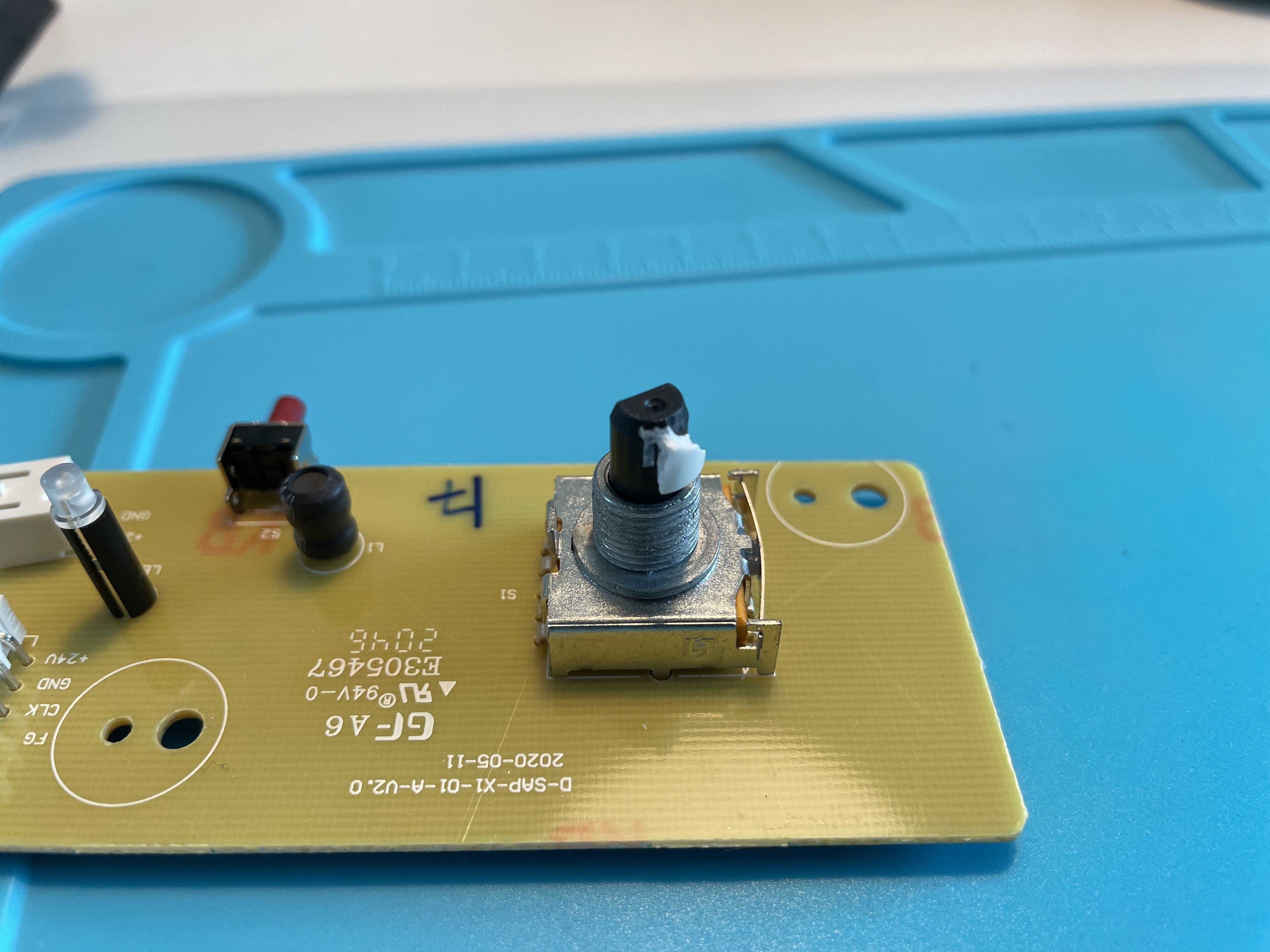
Loose the two screws fixing the PCB and pull out the knob on the other side. Below the knob is a flat nut you have to remove. Now take out the PCB and disconnect the two connectors.

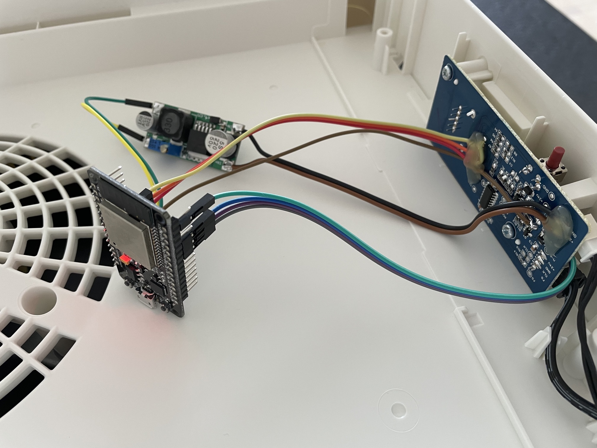
First, solder some wires to the back of the socket where 24V is connected to the PCB. This wire goes to the step-down converter where it is converted to 5V and connected to the Wemos 5V input.

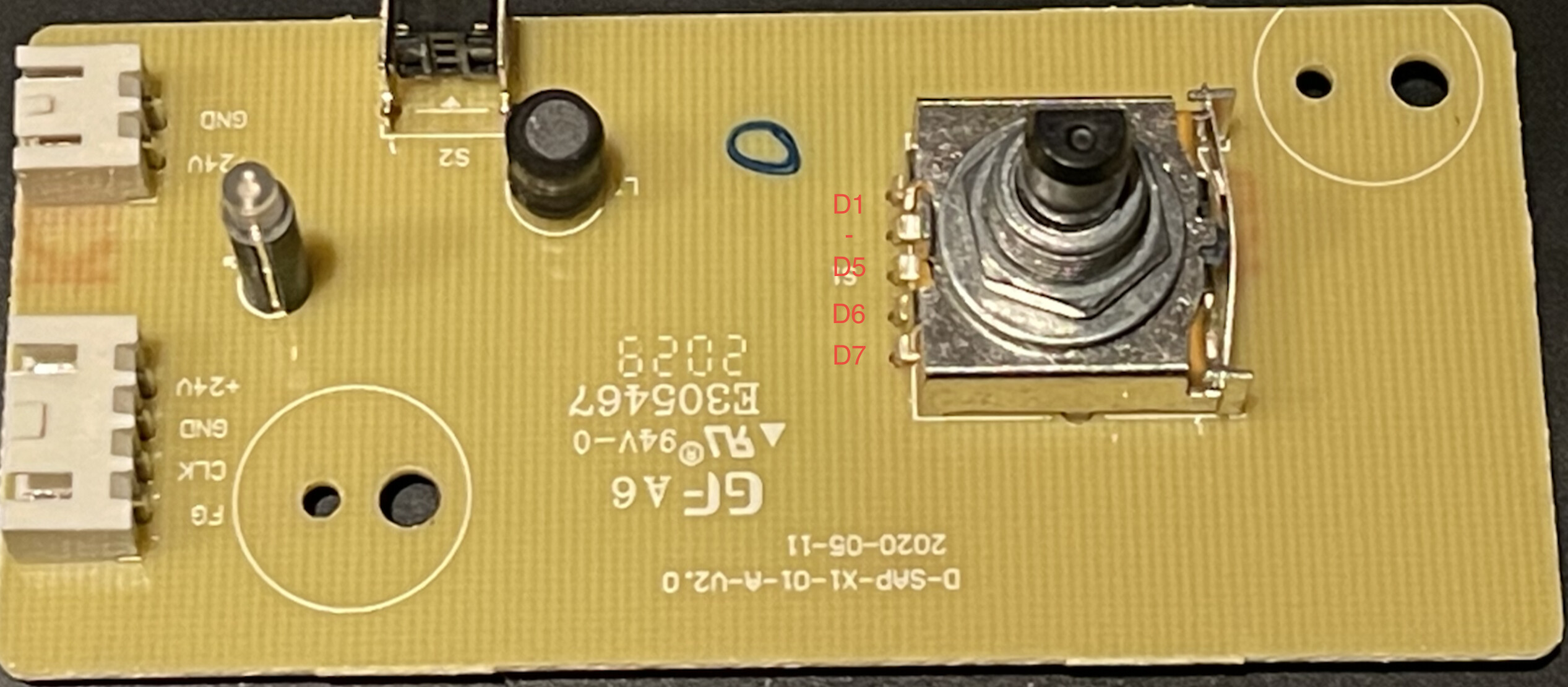
On the top side of the PCB (where the knob was), cut away the connectors for the rotary switch near the PCB (see picture for which legs you have to cut). Take a sharp side cutter and cut each leg individually next to the PCB. Bend the legs up and solder a wire to each of them. Sorry for the bad picture, I took it after applying hot glue… You don’t need to solder a wire to the leg opposite to the small red push button on the PCB – only 4 are needed here. Connect them to D1, D5, D6, D7 on the Wemos. D7 ist next to the one we don’t connect.

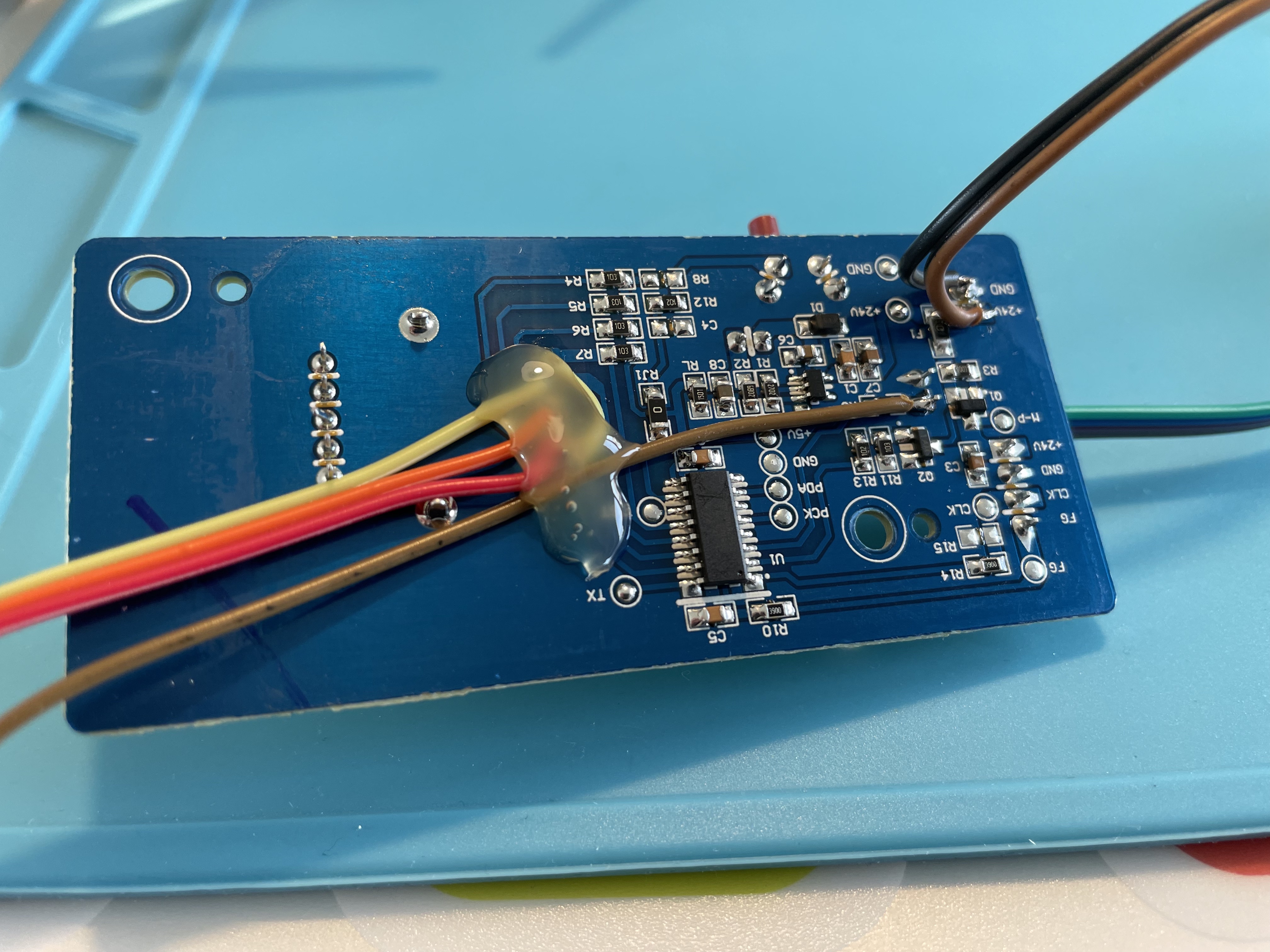
On the other side take out the remaining parts from the rotary switch you cut on the other side to make the holes free. Solder 4 wires on them. One is a bridge to ground, the others also connect to the Wemos (see label on the following picture). The last wire needs to be soldered to the LED or the resistor next to it (red circle on image).

It looks like the controller on the PCB checks all the positions of the rotary switch from highes power to off. Highest value “wins”. So we don’t ever need the actively select the “off”-setting. This is the one we connected to Gnd. Don’t worry about the “short” to Gnd. This is how the rotary switch worked too.

That’s it! Secure all the wires using hot glue and put all the parts next to the existing PCB. I managed to put the step-down converter behind the Wemos D1 mini, it’s barely visible. Use some more hot glue to fix it to the case. Make sure you don’t short out anything.

Before closing it, upload following ESPHome configuration to the Wemos.

esphome:
  name: $devicename
  platform: ESP8266
  board: d1_mini

substitutions:
  devicename: esp82-fornuftig1
  friendly_name: FORNÜFTIG

# Insert your SSID and Your PWD after inital setup
wifi:
  networks:
    - ssid: !secret wifi_ssid
      password: !secret wifi_password

# Enable logging
logger:
  logs:
      # Make adc input less verbose
      adc: INFO

# Enable Home Assistant API
api:
  password: xxxxxxxxxxx

# Enable OTA upgrade
ota:
  safe_mode: True
  password: xxxxxxxxxxx

sensor:
  # Read LED from adc input 10 times per second
  - platform: adc
    pin: A0
    internal: true
    id: led_internal
    update_interval: 100ms
    accuracy_decimals: 1
    filters:
      - delta: 0.1
    on_value:
      if:
        condition:
          lambda: 'return x < 0.2;'
        then:
          - binary_sensor.template.publish:
              id: led_sensor
              state: OFF
        else:
          - binary_sensor.template.publish:
              id: led_sensor
              state: ON

binary_sensor:
  - platform: template
    id: led_sensor
    name: "friendly_name Filter"
    device_class: problem
  - platform: gpio
    internal: true
    id: in_d1
    pin:
      number: D1
      mode: INPUT_PULLUP
      inverted: True
    on_press:
      - fan.turn_off:
          id: fan_internal
  - platform: gpio
    internal: true
    id: in_d5
    pin:
      number: D5
      mode: INPUT_PULLUP
      inverted: True
    on_press:
      - fan.turn_on:
          id: fan_internal
          speed: 1
  - platform: gpio
    internal: true
    id: in_d6
    pin:
      number: D6
      mode: INPUT_PULLUP
      inverted: True
    on_press:
      - fan.turn_on:
          id: fan_internal
          speed: 2
  - platform: gpio
    internal: true
    id: in_d7
    pin:
      number: D7
      mode: INPUT_PULLUP
      inverted: True
    on_press:
      - fan.turn_on:
          id: fan_internal
          speed: 3

output:
  - platform: gpio
    pin: D2
    id: gpio_d2
    inverted: true
  - platform: gpio
    pin: D3
    id: gpio_d3
    inverted: true
  - platform: gpio
    pin: D4
    id: gpio_d4
    inverted: true
  - platform: template
    id: fan_out_internal
    type: float
    write_action:
      if:
        condition:
          lambda: 'return state < 0.1;'
        then:
          - output.turn_off: gpio_d4
          - output.turn_off: gpio_d3
          - output.turn_off: gpio_d2
        else:
          - if:
              condition:
                lambda: 'return state < 0.4;'
              then:
                - output.turn_on:  gpio_d4
                - output.turn_off: gpio_d3
                - output.turn_off: gpio_d2
              else:
                - if:
                    condition:
                      lambda: 'return state < 0.7;'
                    then:
                      - output.turn_off: gpio_d4
                      - output.turn_on:  gpio_d3
                      - output.turn_off: gpio_d2
                    else:
                      - output.turn_off: gpio_d4
                      - output.turn_off: gpio_d3
                      - output.turn_on:  gpio_d2

fan:
 - platform: speed
   output: fan_out_internal
   id: fan_internal
   name: "$friendly_name Fan"
   speed_count: 3

Test it out! The rotary switch does still work but it is also possible to control it from within Home-Assistant. The rotary switch will (of course) not move when controlled from Home-Assistant. But as soon as you move the switch again the corresponding setting will be used.

My first tutorial here, so please be gentle :). Feedback welcome!

Edit: See post IKEA FÖRNUFTIG in Home-Assistant - #32 by RubenKelevra about how to integrate it into energy monitoring.

36 Likes

Nice work, but on the back of the pcb there is a 5+ pin. Doesn’t it work without a step down?

Thanks :slight_smile:

Yes, there is a 5V test point there. According to the Reddit post where I got my inspiration from, this 5V pin is not able to deliver the power needed by an ESP8266. It may work with some additional capacitors… I haven’t tested it myself.

Okey, was hoping to solder one less thing. But then I’ll also use a stepdown :slight_smile:

hello, sorry I do not understand exactly where I am D1, D5, D6 and D7 have to solder.

could you maybe explain this to me in more detailed.

So I have to unsolder the pins of the rotary switch and solder on the PCB with D2 D3 and D4 and the bridge, that is obvious to me from the picture.


or is that correct?

Thanks for your help and tutorial

Sorry, I wasn’t too specific about these pins. I closed my device before checking if the pictures are useful and let’s be honest, the one with the rotary switch isn’t.

You almost got it :slight_smile: . There are 5 pins on this side of the rotary switch but it is only a 4 position switch. So one of these pins is not needed for our use-case. Looking at the bottom of the PCB you see that one pin (marked with red circle) is directly connected to Gnd. This is the pin you don’t need!

Bildschirmfoto 2021-07-01 um 14.51.24

So, try to recap it more clearly.

First, make sure the legs of the rotary switch are no longer connected to the traces on the PCB. I cut them on the top side and flipped the legs up a bit. From the bottom side, remove what stayed in the PCB from the legs you just cut off.

Trying to remember if it was from top to bottom or from bottom to top… I’m quite sure it should be like this:

I hope this helps… Could you please make a nice picture of the rotary switch legs when soldered to the wires? So I could update the initial post to make it more clear.

4 Likes

I just replaced the picture in the initial post. This one should show it better.

The guide worked well, you could also put a little textbox on which pin goes to the led A0 :slight_smile: and point out that the legs are quite difficult to cut without the correct tools, I accidentally destroyed my D6 :smiley: But it works with home assistant and kinda working with the knob, I’ve sat both input d5 and d6 to fan speed 1 and then d7 to fan speed 2 (speed 3 is so loud anyway :slight_smile: ) .

I also added the friendly name in my entities, and added a restart entity

...
binary_sensor:
  - platform: template
    id: led_sensor
    name: "$friendly_name Filter"
    device_class: problem

...

fan:
  - platform: speed
    output: fan_out_internal
    id: fan_internal
    name: "$friendly_name Fan"
    speed_count: 3

switch:
  - platform: restart
    name: "$friendly_name Restart"
1 Like

Thank you for your suggestions and sorry for the broken leg…

I updated the first post to include your suggestions.

Have fun with automating FÖRNUFTIG :smiley:

3 Likes

Thanks for the great instructions and example YAML. I used a DOIT ESP32 DEVKIT V1 board and LM2596 DC-DC converter. My FÖRNUFTIG produced week 13, 2021 had a bit of glue to keep the adjustment knob in place. It required quite a lot of force and broke the plastic where glued. Hot glued it back on without issues.

A few photos from the transplant:

6 Likes

Neat!

Is there a chance to return the power consumption as well somehow for the energy panel?

The power consumption per setting has been measured by a German test:

  • Step 1: 1.5 W
  • Step 2: 6.5 W
  • Step 3: 16 W

Interesting idea. Do you have an links where this is described? I only found this page: Integrating individual device energy usage - Home Assistant

Do we need a simple sensor of type power? If yes, this should be quite easy to implement.

Edit: Added a simple sensor to return expected power usage:

esphome:
  name: $devicename
  platform: ESP8266
  board: d1_mini

substitutions:
  devicename: esp82-fornuftig1
  friendly_name: FORNÜFTIG

# Insert your SSID and Your PWD after inital setup
wifi:
  networks:
    - ssid: !secret wifi_ssid
      password: !secret wifi_password

# Enable logging
logger:
  logs:
      # Make adc input less verbose
      adc: INFO

# Enable Home Assistant API
api:
  password: xxxxx

# Enable OTA upgrade
ota:
  safe_mode: True
  password: xxxx

sensor:
  # Read LED from adc input 10 times per second
  - platform: adc
    pin: A0
    internal: true
    id: led_internal
    update_interval: 100ms
    accuracy_decimals: 1
    filters:
      - delta: 0.1
    on_value:
      if:
        condition:
          lambda: 'return x < 0.2;'
        then:
          - binary_sensor.template.publish:
              id: led_sensor
              state: OFF
        else:
          - binary_sensor.template.publish:
              id: led_sensor
              state: ON
  - platform: template
    name: Power Usage
    id: power_usage
    device_class: power
    state_class: measurement
    unit_of_measurement: W

binary_sensor:
  - platform: template
    id: led_sensor
    name: "$friendly_name Filter"
    device_class: problem
  - platform: gpio
    internal: true
    id: in_d1
    pin:
      number: D1
      mode: INPUT_PULLUP
      inverted: True
    on_press:
      - fan.turn_off:
          id: fan_internal
  - platform: gpio
    internal: true
    id: in_d5
    pin:
      number: D5
      mode: INPUT_PULLUP
      inverted: True
    on_press:
      - fan.turn_on:
          id: fan_internal
          speed: 1
  - platform: gpio
    internal: true
    id: in_d6
    pin:
      number: D6
      mode: INPUT_PULLUP
      inverted: True
    on_press:
      - fan.turn_on:
          id: fan_internal
          speed: 2
  - platform: gpio
    internal: true
    id: in_d7
    pin:
      number: D7
      mode: INPUT_PULLUP
      inverted: True
    on_press:
      - fan.turn_on:
          id: fan_internal
          speed: 3

output:
  - platform: gpio
    pin: D2
    id: gpio_d2
    inverted: true
  - platform: gpio
    pin: D3
    id: gpio_d3
    inverted: true
  - platform: gpio
    pin: D4
    id: gpio_d4
    inverted: true
  - platform: template
    id: fan_out_internal
    type: float
    write_action:
      if:
        condition:
          lambda: 'return state < 0.1;'
        then:
          - output.turn_off: gpio_d4
          - output.turn_off: gpio_d3
          - output.turn_off: gpio_d2
          - sensor.template.publish:
              id: power_usage
              state: 0.5
        else:
          - if:
              condition:
                lambda: 'return state < 0.4;'
              then:
                - output.turn_on:  gpio_d4
                - output.turn_off: gpio_d3
                - output.turn_off: gpio_d2
                - sensor.template.publish:
                    id: power_usage
                    state: 1.5
              else:
                - if:
                    condition:
                      lambda: 'return state < 0.7;'
                    then:
                      - output.turn_off: gpio_d4
                      - output.turn_on:  gpio_d3
                      - output.turn_off: gpio_d2
                      - sensor.template.publish:
                          id: power_usage
                          state: 6.5
                    else:
                      - output.turn_off: gpio_d4
                      - output.turn_off: gpio_d3
                      - output.turn_on:  gpio_d2
                      - sensor.template.publish:
                          id: power_usage
                          state: 15

fan:
 - platform: speed
   output: fan_out_internal
   id: fan_internal
   name: "$friendly_name Fan"
   speed_count: 3
2 Likes

IMHO we are still in early days of power management. I was able to make it happen but I’m not happy with the result as it requires too many steps. Maybe someone has a better solution.

  1. First I added the current power consumption to ESPhome as shown above.
  2. Add a new integration sensor in configuration.yaml:
sensor energy:
  - platform: integration
    name: power meter test
    source: sensor.power_usage
    unit_time: h
    round: 2
  1. Use customization to add some attributes to the new integration sensor:
sensor.power_meter_test:
  device_class: energy
  state_class: measurement
  last_reset: '1970-01-01T00:00:00+00:00'
  1. Restart Home-Assistant and go to the Energy-Settings. Add the new device.

I don’t think it helps to integrate the value on the ESPhome device as I can’t find a way to use the bootiup-time of the microcontroller as last_reset for the total energy consumption. ESPhome allows the integral to be persistent but this will wear-out the flash memory quite fast.

1 Like

Why do i get this error when im trying to upload?

[speed_count] is an invalid option for [fan.speed]. Did you mean [speed_command_topic], [speed]?
speed_count: 3 [source ikea.yaml:153]

According to Speed Fan — ESPHome speed_count is valid. Do you have a current version of ESPhome? I’m on Version 1.20.4.

I’ve ignored an error while updating esphome, so i was still stuck on 1.16.x… working now with the latest update :slight_smile: thanks

1 Like

Hey @tht, thanks a lot for the instructions! Been wanting to do this project for a while, now I did and I’m facing some issues.
The rotary switch is behaving a bit weird, I can’t seem to turn the air purifier off anymore and also some positions don’t really adjust the fan speed. And most strangely, I need to kind of “over-toggle” the switch to reach some positions. I could’ve possibly damaged it while working on the legs / soldering… damn!

Or maybe I connected something wrong. Do all of the legs of the rotary switch have to be cut? Or only those relevant to connect to the ESP (D1/5/6/7). You mentioned that one leg next to D7 - does it have to be cut as well? Currently I did not do that, but I added the bridge to GND on the backside.

Apart from this, nothing is showing up in home assistant, although I successfully flashed everything via ESPHome and the ESP reports to be online. Shouldn’t a new device appear in HA? (I’ve tried restarting everything already)

Thanks a lot, again!

Maybe this custom component can help? :thinking:

Hi @bttrsh, sorry to hear about the issues you have. It’s hard to tell from a distance what the issue could be. Maybe it helps if I give you some insights about how it should work so you can measure it out.

The rotary switch has 4 positions and is connected to 4 inputs on the original controller. All the inputs are pulled up by the resistors you see on the PCB. The rotary switch connects one of the inputs to Ground to select it. You should be able to verify these voltages. I don’t know if the last leg on the rotary switch needs to be connected to Ground or not. You should be fine when left connected. Also, look at the fantastic pictures provided by @lassebm. Check if you connected the wires to the same place.

Are you sure the code is uploaded to the Wemos D1 Mini? As soon as you did the modification the rotary switch is no longer directly connected to the original PCB. The Wemos D1 Mini needs correct software to act as bridge between the rotary switch and the original PCB.

Lastly, Home-Assistant should show the new ESPhome module as soon as it is connected to the network. Check Settings/Integrations.

Hope this helps and you are able to make it work.

homeassistant-powercalc should do the trick. It does support fans and this hack integrates the IKEA device as fan into Home-Assistant. So, it should work just fine.

2 Likes