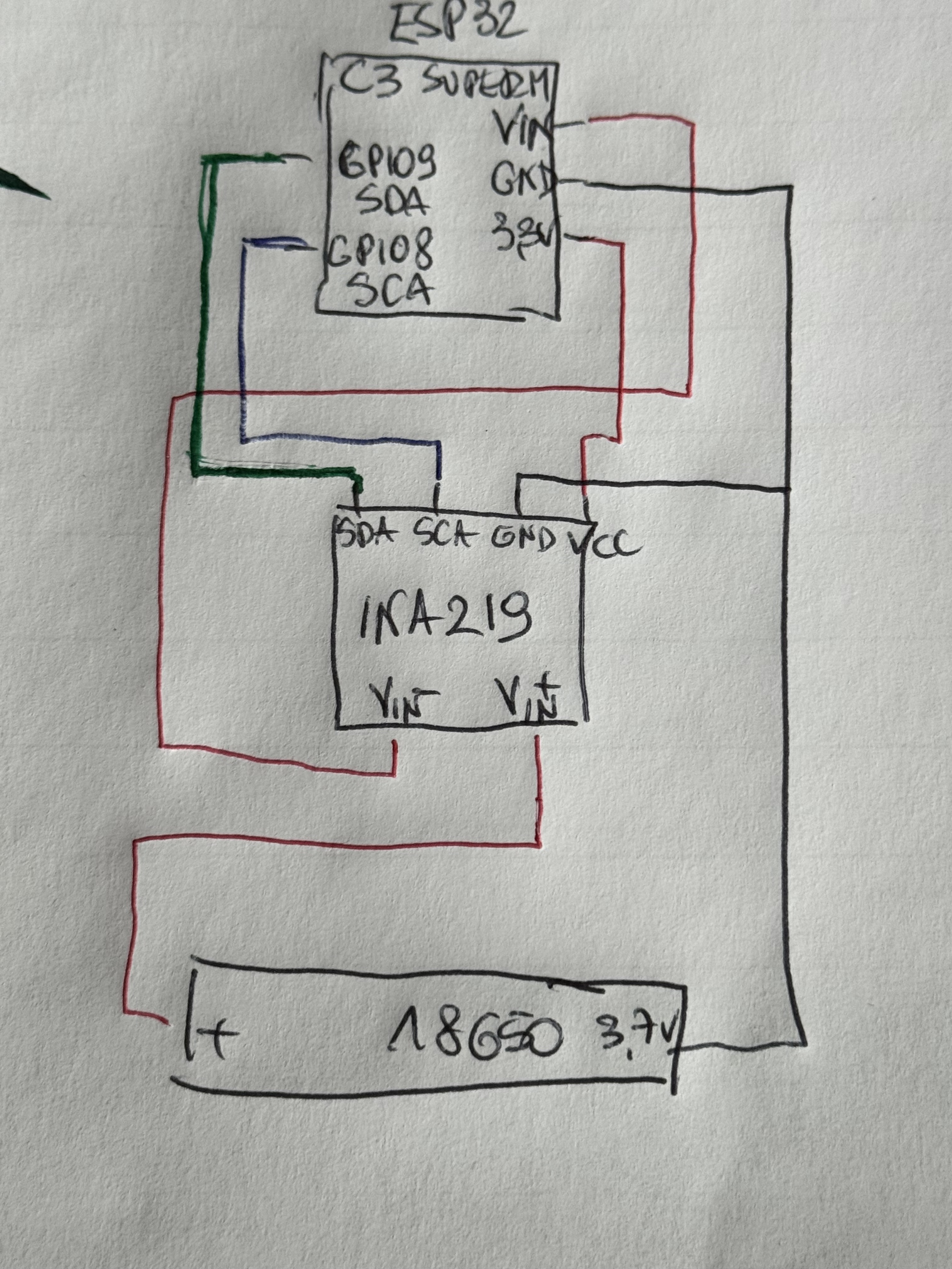
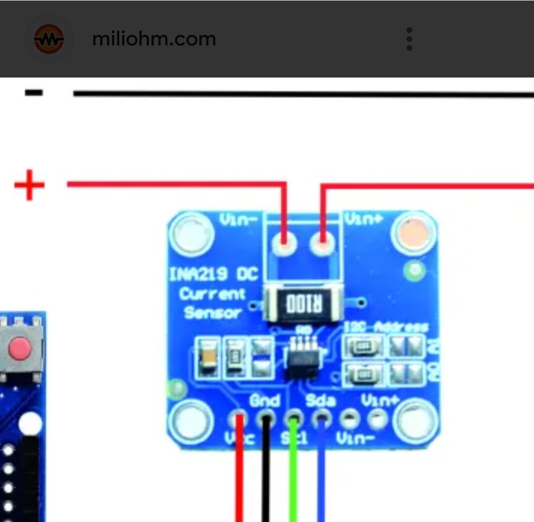
(Sorry for manual sketch, just wanted to quickly ask for advice).
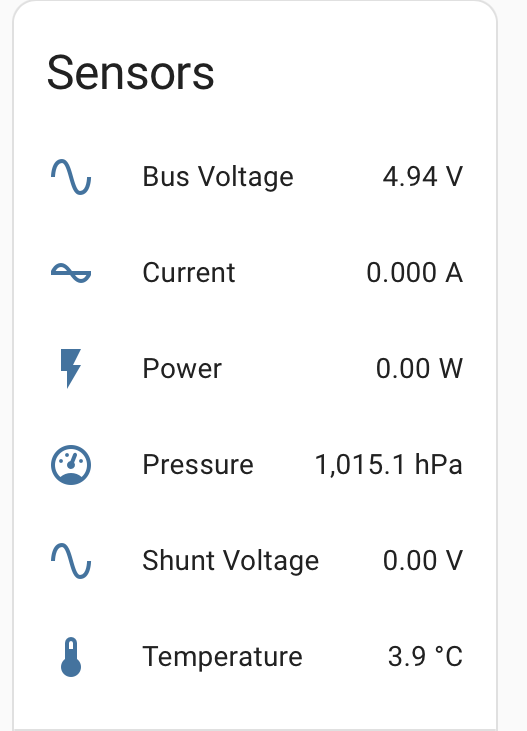
There is communication and everything seems to work perfectly but I have an impression that I am measuring not the proper voltage as it reports basically all the time 4.93-4.92V and then the battery dies suddenly, when measured with multimeter it showed 2.9V. How do I need to change my wiring to measure the battery voltage?
The sketch is very good. Can I ask why dont you use a simple voltage divider circuit and an adc pin on the esp32 c3 rather than use more energy on the ina219?
Just for experimenting. The ESP in final version would go into deep sleep. But still my question is valid - I think I am not measuring the battery voltage, seems like I am measuring the board voltage I suppose… ?
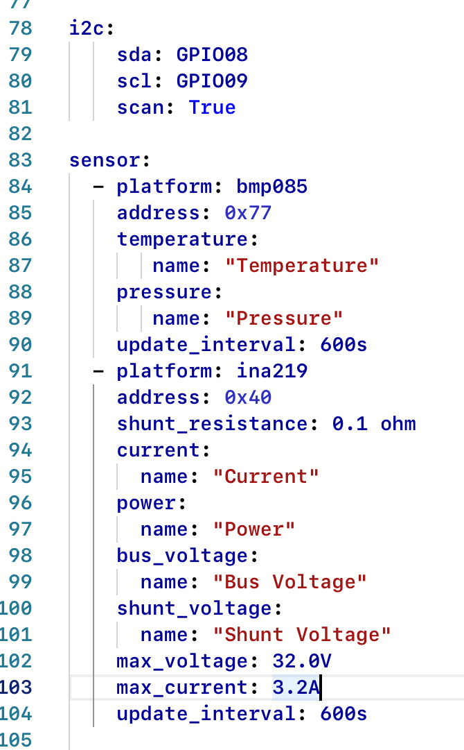
Theoretically yes but esp32 converts the power in voltage to 3.3V. So the whole circuit works perfectly fine. I have a bmp 085 hanging on the same gpios with different address than ina and I have everything I want from this test. Except I just can not get the proper voltage measured.
I use one to measure voltage in a gate buzzer.
I still think voltage divider with adc in battery powered device will save more battery but op just wants to get it working for learning purposes. Even in deepsleep the ina will be powered.
Until it doesn’t.
When your battery voltage goes below 3.3V+Vdif you are operating in “gray zone”, LDO can’t regulate the voltage correctly. Ina might not be happy without stabile >3V supply.
Try how it works with fully charged battery.
What? Do you understand the difference from voltage and current? You are measuring the shunt voltage which is directly relatable to the current through the shunt. It will be constant as long as the voltage is sufficient to run the ESP. When the voltage gets too low for the ESP to function, it shuts down and the current drops to nearly zero.
Have you read the whole topic or are you just jumping on a high horse after reading one phrase, which might be slightly unfortunate as I am not a native English speaker? Have you got a solution for the problem I am trying to find and understand or are you here just to show that you know more? Have you read the community rules? If any of the answers is „no” than please leave your comments somewhere else.
The battery is indeed in the charger shield. I need to make sampling more frequent to see the correlation with the battery voltage and the level of voltage from the shield. Thanks for turning my attention to this.