I noticed online a few posts around setting up mini switches, (for example the ZBMini) in the switch of a lighting circuit instead of in the ceiling rose.
This may work in some places with stud walls, but if your house is made of brick and mortar (even the internal walls). Then you’ll likely not want to chisel out the extra depth whilst damaging the decor and making a huge mess. Whilst insisting to your other half that this is all going to be amazing when it works.
So for me, opening up switches and modifying them to place the switch just wasn’t going to work.
In this blog, I’ll detail how to connect a smart switch to your light ring via the ceiling rose. I’ll talk about my reasoning behind some of my choices, and more importantly, it’ll be a reference for me later on. When i tackle the dimmable LED downlights.
Obligatory: I am not an electrical engineer and this is my observation only, do not attempt to repeat this unless you feel confident/competent enough to do so.
Note this is a non-dimmable setup. the smart switch “controls” the physical switch so using this setup will effectively stop any dimmable functionality
Note this is for UK light rings in the “Loop” configuration.
Note I’ll be using the UK new wiring standard throughout all my diagrams. But for the sake of simplicity i’ll refer to them as “live colour”, “neutral colour”.
Setting up and planning
My main thought process is, how can I do this safely, and with minimal disruption. And the answer was to place the switch in a junction box, and feed the wires into the ceiling rose. So it ends up looking a little something like this:

Whats going on here?
- The circuit comes in from the left and feeds into the ceiling rose (loop in)
- The switch feeds its in/out/switch wires into the ceiling rose
- The circuit continues on its lovely loop around the house. (loop out)
This means I can place the switch in an accessible place in the loft, and could even place additional monitors on it to check its temperature (if your switch doesn’t come with that stuff built in).
Ok great, but really what people are afraid of tackling is the ceiling rose. So lets take a closer look.
Ceiling rose pre-switch insert
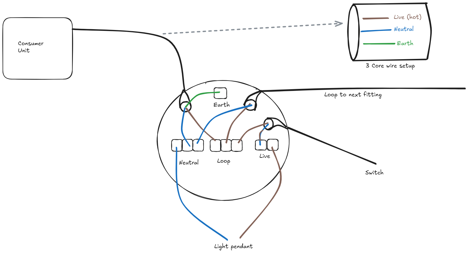
So most ceiling roses will use a standard loop in system like above. I’ve actually messed up this image. the loop out should also be attached to the earth terminal to complete the earth loop.
But slight mess up aside. The circuit comes in from the consumer unit. Goes down into ceiling rose and terminates at the loop terminal. From the loop terminal it will go on to the loop to continue the circuit. It will also go on to the switch circuit:

The switch circuit can confuse people because typically a standard 3 core cable will be used (which will have a different colour for live, neutral and earth) and the wire that comes back will be neutral coloured. Why? Because you can’t use the live (that was used to come into the switch, and you can’t use the earth, that’s a safety wire, its unsleeved and would be incredibly dangerous to use. So the only available wire is the one designated for neutral. To accommodate this. Most engineers will put a live coloured sleeve on it to let you know its actually live.

So how can we put the smart switch in?
Well it makes sense to not force the loop to go through the smart switch, and we of course want to have use of the physical “dumb” switch. So we actually want to insert the smart switch circuit “after” the loop in terminal so to speak. which would look something like this:
Ceiling rose with smart switch insert

please note the earth for live in and live out should be terminated at the earth terminal in the ceiling rose. I have not added it here because it would have made the diagram hard to follow
So in the picture above we can see the smart switch has taken the live from the physical switch:

and taken the neutral that was being fed directly into the light pendant.
This is our “Live in”, typically L1 or Lin on smart switches, with the neutral going to the corresponding neutral terminal
And what about S1 and S2? Well that is now a special circuit used exclusively between the smart switch and the physical switch:

Note that usually this special circuit usually can’t take a live load. most (but please check your specific switch) can handle at most 5v. Also, if your smart switch is putting more current into the circuit, then it will need to be earthed So do check.
These wires go to S1 and S2 respectively.
So now, the smart switch is hot, but its not doing anything. we haven’t wired up the output wires yet. Usually L2 or Lout and the remaining N
This goes back out to the ceiling rose and on to the light pendant.
But whats going on with that smart switch?

Well, its in a junction box. This keeps it relatively safe from the usual dust and crap that gets thrown in the loft. But also - and infinitely more importantly - it allows us to complete the earth circuit Remember, if the special switch circuit uses a large current, it will also need to be earthed.
I used this guy as a reference. So if you are still nervous about tackling a ceiling rose with a smart switch, be sure to check him out as his explanations are clear and concise.