I’ve been trying out this ESP 433MHz Finoffset sensors on a Sonoff RF bridge (rewired to bypass the RF chip). I have managed to get it to read my 433MHz humidity and temperature sensors. However since I have 3 of them I need to figure a way to sort them in manner that they show up as separate sensors in Home Assistant. As off now all sensor data is in a big pile…
Any progress on your project?
Nothing yet. I decided I want to do a wired solution using CAT5 and I’ve determined the location. I’m going to use RJ-45 and RJ-11 to run power and signal data to the location. On May 2nd I purchased RJ-11 and RJ-45 jacks along with some RJ-45 breakout PCBs from AliExpress and they still haven’t arrived. I think the shipping industry has been shocked by COVID-19 and it seems that AliExpress has extended all of the buyer protection to account for this. When this stuff arrives, I’m planning on buying the $65 weather station on Sparkfun’s website. Along with some of their RJ-11 breakout boards (I couldn’t find those an AliExpress for some reason).
@bassicrob, I just got the weather kit today and I’m messing around with it now. I’m trying to figure out what the wiring looks like for the wind direction. I realized that moving the vane around changes the resistance measurement between two of the pins on the RJ11 plug.
Do I take one of those pins to a A0 and the other to 3.3V? By the way the resistance_sensor option in ESPHome is written it sounds like I need to create a voltage divider circuit and I can label the resistor switch with the fixed value, is that what you did? I looked at the values in the comments and I couldn’t line up your voltage/resistance with the 10kΩ you listed.
I also tried to reference the “wiring” URL from your Reddit post (https://shop.switchdoc.com/collections/weather) but the content won’t display for me. It just says Weather at the top and then shows all the ads. It shows that for all five pages so something must be wrong with switchdoc.
Anyway, I’m really excited to try this bad boy out. I got an AS3935 lightning sensor to go with it and I’m waiting on a BME280 to integrate as well. Hopefully, I can get them all working together on one solution…
Thanks,
-Greg
That’s awesome @SpikeyGG. IMO it is easier using the RJ-45 / RJ-11 keystones and self-terminated cables, but the breakout boards will work just as well. I already had a bunch of those on hand.
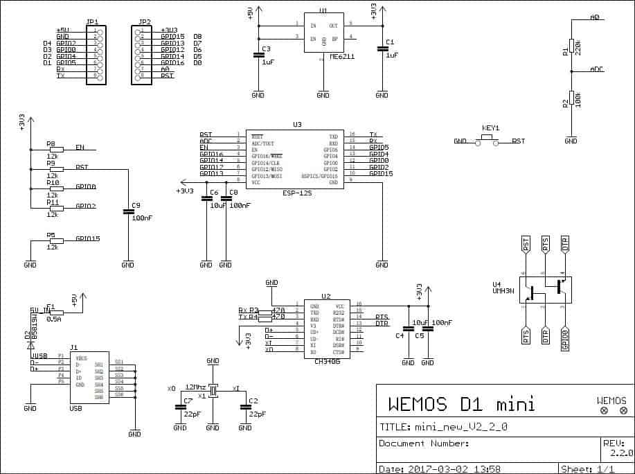
As far as my reference readings, a number of factors may cause a different reading. Wire length and type will affect your readings, which may be one reason you are getting different numbers. I set mine up on the bench with estimated lengths of wire and set the vane in position with tape to record values. If using the Wemos D1 Mini, it already has a voltage divider circuit on A0 and my 10k resistor is based on that (220k + 100k) being already present on the board (See here, top right corner). Other NodeMCU’s may not have this built in. One wire will go to 3.3v and the other to pin with 10k resistor back to 3.3v. IIRC I realized I did something incorrectly, but had already calibrated my values and it worked, so… 
What is important is setting the
accuracy_decimals: 3 ##or more
in your ESPHome sketch. This will give you better resolution for setting the ranges without overlapping. The link to the datasheet is here (PDF) if you haven’t found it already.
Direction is just a bunch of reed switches. Mine did not match their readings either, but they reference a 5v base voltage with a 10k resistor, other rebranded datasheets for the same product had a 3.3v reference voltage, so again HAHA
Mine’s still going strong. Only issue so far is the BME temps are incorrect on hot days and worse on hot sunny days. Radiation shield and fan would solve this issue on a build.
Good luck!!
Woah! I didn’t see that PDF. I looked at my pre-hookup measurements and they’re pretty much exactly what that doc shows but I didn’t realize that there were 16 variations… that’s crazy. I’m going to try to tune that in, and I’ll send the codes if I can get it working correctly.
Good to know about the wire length, I’ll watch out for it.
So I got this thing hooked up and working but when I swap out the ethernet cable for a longer one, ESPHome says it can no longer connect to the i2c devices.
Short (4ft) Ethernet Cable
[10:06:59][D][sensor:092]: 'Receiver Uptime Raw': Sending state 616.76501 s with 0 decimals of accuracy
[10:07:01][D][ads1115:163]: 'Wind Vane Raw': Got Voltage=4.095875V
[10:07:11][D][ads1115:163]: 'Wind Vane Raw': Got Voltage=4.095875V
[10:07:21][D][ads1115:163]: 'Wind Vane Raw': Got Voltage=4.095875V
[10:07:23][D][ads1115:163]: 'Receiver Illuminance': Got Voltage=0.197063V
[10:07:28][D][pulse_counter:159]: 'Rain Pulses 1min': Retrieved counter: 0.00 pulses/min
[10:07:28][D][sensor:092]: 'Rain Pulses 1min': Sending state 0.00000 in with 3 decimals of accuracy
[10:07:28][D][sensor:092]: 'Rainfall Per Minute': Sending state 0.00000 in with 5 decimals of accuracy
[10:07:29][D][sensor:092]: 'Receiver Uptime Raw': Sending state 646.75702 s with 0 decimals of accuracy
[10:07:31][D][ads1115:163]: 'Wind Vane Raw': Got Voltage=4.095875V
[10:07:32][D][pulse_counter:159]: 'Wind Sensor': Retrieved counter: 0.00 pulses/min
[10:07:32][D][sensor:092]: 'Wind Sensor': Sending state 0.00000 mph with 1 decimals of accuracy
Long (40ft) Ethernet Cable
[10:09:45][E][ads1115:077]: Communication with ADS1115 failed!
[10:09:45][W][i2c:070]: Received NACK on transmit of address 0x48
[10:09:52][W][i2c:070]: Received NACK on transmit of address 0x48
[10:09:54][D][pulse_counter:159]: 'Rain Pulses 1min': Retrieved counter: 0.00 pulses/min
[10:09:54][D][sensor:092]: 'Rain Pulses 1min': Sending state 0.00000 in with 3 decimals of accuracy
[10:09:54][D][sensor:092]: 'Rainfall Per Minute': Sending state 0.00000 in with 5 decimals of accuracy
[10:10:00][D][sensor:092]: 'Receiver Uptime Raw': Sending state 55.38400 s with 0 decimals of accuracy
[10:10:02][W][i2c:070]: Received NACK on transmit of address 0x48
[10:10:03][D][pulse_counter:159]: 'Wind Sensor': Retrieved counter: 0.00 pulses/min
[10:10:03][D][sensor:092]: 'Wind Sensor': Sending state 0.00000 mph with 1 decimals of accuracy
I tried putting level shifters before the transmission lines thinking that 3.3V was too low and I was losing signal, so stepping it up to 5V for transmission but it doesn’t seem to help. Any ideas?
I need to use a 35 foot cable to get to where I want my weather station. 
I’m trying to figure out how to draw a schematic so I can share the wiring diagram but I haven’t been able to find a good way to create a diagram…
Originally, I bought one of those purple PCB AS3935 lightning sensors (as shown on the esphome AS3935 page). The esp8266 could see it on i²c bus, and HA created three entities (Distance Storm, Lightning Energy, and Storm Alert) for it. The problem is that those entities haven’t registered anything and we did have a single thunderstorm pass through recently. I also tried to test it out with a barbecue lighter and it didn’t respond to anything.

I more recently purchased an official red PCB SparkFun AS3935 device to see if I could make it work any better.

With this new one, I’ve found that I can get the esp8266 to see it on the i²c bus and HA creates all the entities like the purple one. However, I’ve noticed when I try the barbecue lighter near it and watch the logs I see this set of two entries every time I pull the trigger:
[09:29:28][W][i2c:070]: Received NACK on transmit of address 0x03
[09:29:28][W][as3935_i2c:029]: Read failed!
This makes me think that something is actually working but I still don’t know what it means…
Regarding the distance/power/data issue, you might consider the Olimex-ESP32-POE-ISO
POE will easily run much longer than 50 feet. 
That looks like a pretty cool device @FredTheFrog!
@SpikeyGG, one thing I discovered in several of my IoT creations and CAT-5, is be mindful of which wire pairs are used. You don’t want to pair 5v-Gnd on say orange and orange stripe, and the same for data connections (ie SDA SCL). I think I got lucky with my wire selection for this project, but have had bad connections on other projects using CAT-5 wire pairs. I usually run 1 like pair for power and 1 like pair for ground now, leaving 2 pairs left for sensors. IIRC, I ran SDA and SCL each on their own pair for this project, as I have a separate CAT-5 specifically for the I2C bus, and another run for the analog sensors/LED. Then again, I2C is designed for on-PCBoard comms and not long distance, so your luck may also be related to may other factors.
Hope you’ve made further progress with this fun project! Mine is still going strong!! Coincidently I just received some lux sensors to test in the build. I also need to mount everything in a box and on a pc board! I did add an LCD which prints out temp, humidity, wind speed, gust, and pressure.

Hey @bassicrob, I did get mine together around July of 2020 and it’s been working since then. However, because I’m trying to run i2c over cat5e run of ~40ft, I’m getting a lot of this:
[08:02:24][W][i2c:086]: Requesting 2 bytes from 0x48 failed!
[08:02:24][W][i2c:086]: Requesting 2 bytes from 0x48 failed!
[08:02:25][W][i2c:086]: Requesting 2 bytes from 0x48 failed!
[08:02:25][W][i2c:086]: Requesting 2 bytes from 0x48 failed!
[08:02:25][W][i2c:070]: Received NACK on transmit of address 0x48
[08:02:25][W][i2c:086]: Requesting 2 bytes from 0x48 failed!
[08:02:25][W][i2c:070]: Received NACK on transmit of address 0x48
[08:02:25][W][i2c:070]: Received NACK on transmit of address 0x48
[08:02:25][W][i2c:086]: Requesting 2 bytes from 0x48 failed!
[08:02:25][W][i2c:070]: Received NACK on transmit of address 0x48
[08:02:25][W][i2c:070]: Received NACK on transmit of address 0x48
[08:02:25][W][i2c:070]: Received NACK on transmit of address 0x48
[08:02:25][W][i2c:070]: Received NACK on transmit of address 0x48
[08:02:25][W][i2c:086]: Requesting 2 bytes from 0x48 failed!
[08:02:25][W][i2c:086]: Requesting 2 bytes from 0x48 failed!
[08:02:25][W][i2c:086]: Requesting 2 bytes from 0x48 failed!
[08:02:25][W][i2c:086]: Requesting 2 bytes from 0x48 failed!
[08:02:25][W][i2c:070]: Received NACK on transmit of address 0x48
[08:02:25][W][i2c:070]: Received NACK on transmit of address 0x48
[08:02:25][W][i2c:070]: Received NACK on transmit of address 0x48
[08:02:25][W][i2c:086]: Requesting 2 bytes from 0x48 failed!
[08:02:25][W][i2c:070]: Received NACK on transmit of address 0x48
Which bothers me greatly. However, the 0x48 is my ads1115 which gathers the data from my analog stuff (for illuminance and weather vane direction) and those do give me good values so I think it’s just lots of reports of noise since the i2c signal is too long. For example:

My analog illuminance sensor reporting

Remote sensor array “production” build

Local sensor array “production” build

Remote sensor array “production” build circuit board bare
I still want to fix this so researching, I have found this article on stackechange and purchased a set of P82B96s. They’re not cheap: about $3 per chip but they work. I’ve bread boarded a new design using these chips and it works with a 50 foot cat5 cable! ![]() now I just need to build up the production boards and put it into use.
now I just need to build up the production boards and put it into use.

Bread board mock up using P82B96 chips with 50’ cat5e
I actually got the breadboard done in August 2020 but I haven’t gotten around to actually building the finished product yet. Mainly, because I want to be able to use i2c for everything now including the interrupt on the as3935.
I can put an I/O extender on i2c which would give me access to short distance I/Os on the remote. However, ESPHome does not allow the as3935 interrupt nor pulse_counter inputs to be assigned to IOs on an I/O extender. So, I’ve been stuck. ![]()
Error message:
sensor.pulse_counter: [source /config/esphome/weathernew.yaml:119]
  platform: pulse_counter
  pin:  [source /config/esphome/weathernew.yaml:121]

    [pcf8574] is an invalid option for [pin]. Please check the indentation.
    pcf8574: pcf8574_hub [source /config/esphome/weathernew.yaml:121]
    number: 1
    mode: INPUT_PULLUP
So, does anyone know how I can go about putting pulse_counter inputs and/or the interrupt for as3935 on an I/O extender using ESPHome? ![]()
I actually made a post about this in July of 2020 and didn’t get anywhere with it ![]()
I did find those in my research as well, and since I had plenty of CAT5 cable in hand I decided to just run another line dedicated for the I2C, and another breaking out the Rain, Wind Speed and Direction. I needed one more wire for the status LED so that got it’s own run. I bought some I2C light sensors (VEML6070 & SI1145) for UV and lightning detection, but have not had a chance to toy with them yet. Everything fits within the original housing for RF and batteries, and this addition would require another box. I’ll do that when I situate the station on the roof of the house instead of the garage.
I finally built PCB and a case (of course not finished) for the NodeMCU. I just need to practice my Dremel skills and get some shorter screws for the display mount.


I also did finally update my gist and fork from @mkuoppa who originally got this all to work!!
2 Likes
@bassicrob, this is lookin’ pretty awesome. Do you have a 3D printer? I don’t but these kinds of one-off smart home devices are just begging for 3D printed housings and that’s primarily why I’d want to spend the cash on one. I like the display! I have a few of these little displays hanging around but I’ve only put one of them into production… not a bad idea to put one on the weather station.
A 3D printer would certainly make these things easier to house, @SpikeyGG !! However my wife thinks that it would be yet another time consuming hobby that I don’t need, haha!
Honestly, although they don’t look as good, the project boxes don’t take nearly as long as laying out and assembling the board itself.
1 Like
@bassicrob i used you’re code with the same rain sensor. Got an output like this:
[12:01:14][D][pulse_counter:159]: 'SolarWeatherStation Rain': Retrieved counter: 30.00 pulses/min
[12:01:14][D][sensor:092]: 'SolarWeatherStation Rain': Sending state 10.77763 mm with 2 decimals of accuracy
Perhaps i don’t understand the calculations, but get easily 200mm rain. if i read the local weather authority they talk most of the times about 0,5 - 3 mm ?
I changed the 'update_interval: 2s ’ instead of 60sec, or does it need to be at 60 sec? I need it because of deep sleep entering in around 35 sec.
Thanks
I based my rain sensor code off of what @mkuoppa provided, but converted it to inches. The original metric conversion if that is what you are looking for is commented out in the code. It may explain your excess readings. Sometimes though I will get triggers even on a sunny day. If your mast is not secure the wind may trigger the flap to flip, triggering the reed switch in the rain bucket. This also assumes that your pin is not floating due to cable length or interference. Mine is 50’ and I have no additional resistors on that line.
HI,
Would it be possible to share the wiring schema?
It sounds like, after reading your post about the resistor values for a wind direction sensor that reads line voltage or resistance…that you might have some code you might share for incorporating a spark fun weather station kit wind direction sensor for HA. I have the reference material, and have the example code for arduino IDE which talks about that, but how do I incorporate that into the ESP and HA? I assume it would be as simple as creating a new sensor in the main device’s yaml but I am really new to this platform and could use some cheat sheets.
I have everything else working well, but not sure how to get the direction into HA.
I created my own board with the pull ups…just need to know how to call it into existence on HA.
Thanks.
The resistance values are calculated from the onboard ADC sensor (A0 pin). Depending on your resistor value used for the voltage supply you are sending, line length, and many other variables, your values may differ than those I provided in my code that works on my setup. I’ve calculated those during benchtop tests with a multimeter and ESPHome debug logs to tell me those values are “within range” of the values I should expect when the anemometer is pointed at the indicated direction. Further, the datasheet gives expected value ranges on the A0 pin based on a resistor value.
I suggest setting the vane up on a bench, mark the position of the instrument “North”, connect the wires per the datasheet or my gist with the specified resistor value, and rotate the vane to the other directions recording their values on the A0 pin. Once you’ve determined a range that applies to your setup, you can add those values to the code as indicated in the notes. I do not know how your own designed board is specifically configured to apply it to the config that is working for mine, but I am sure if you read the #comments you can get everything working, as well as the first ~15 or so posts of this thread and the referenced links.
The two links in the 2nd post of this thread provide insight on wiring diagrams and specifically my setup that worked for me. Hopefully you have figured yours out since your post, but if you still need help lmk.