Hello all,
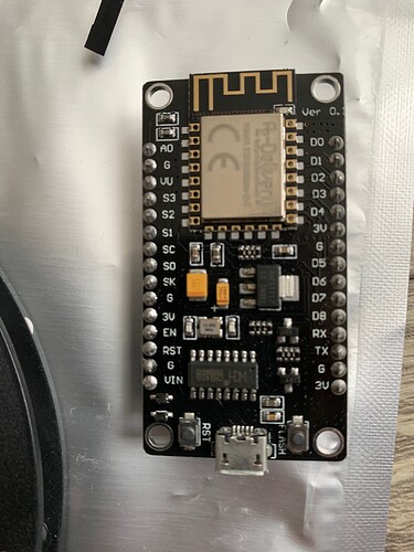
I am trying to setup a esp8266 with a WS2812B.
I flashed the esp with WLED and connected to the WIFI network and HA.
The esp works if I connect it alone to the power source (web page available).
However if I make the connection with the strip, esp and power source, the strip does not light and not even the esp is working (cant connect to IP)
If I disconnect the data cable from the strip, the esp works.
…
I tried 2 different power sources 5V/8A and 5V/50A and 2 strips 150/300 leds.
…
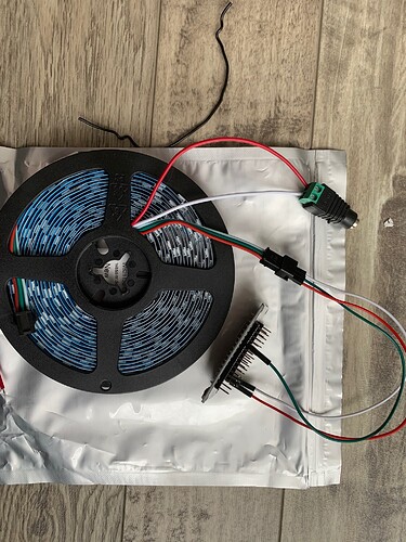
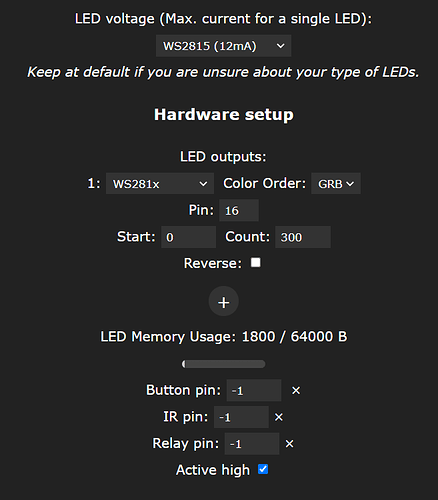
The wiring is like here and is the same on the led specs… the only 2 things that made me worried are that on the strip specs is saying 2.5m long (but ppl on Amazon say is working with 5m) and thge fact that I see on Wled page some setting for the strip tha I did not change …
…
ESP: https://www.amazon.fr/gp/product/B074Q2WM1Y/ref=ppx_yo_dt_b_asin_title_o07_s02?ie=UTF8&psc=1
WS2812B (with mini USB): https://www.amazon.fr/gp/product/B07TMLXWF2/ref=ppx_yo_dt_b_asin_title_o05_s00?ie=UTF8&psc=1
Wires: https://www.amazon.fr/gp/product/B01JD5WCG2/ref=ppx_yo_dt_b_asin_title_o07_s02?ie=UTF8&psc=1
Power 250: https://www.amazon.fr/gp/product/B07Y32NSQG/ref=ppx_yo_dt_b_asin_title_o07_s00?ie=UTF8&psc=1
Power 50: https://www.amazon.fr/gp/product/B083QN65BB/ref=ppx_yo_dt_b_asin_title_o07_s03?ie=UTF8&psc=1
Any idea what could be wrong ?
Thank you!
You might need a level shifter on the data connection.
Google dig uno or similar boards can be found on eBay.
Indeed I’ve seen that on the scheme but it was optional … when is actualy needed ?
PS: I will buy one anyway and try - ty!
I think the output from the esp is 3.3v and the strip is looking for 5v.
I bought this one and loaded sound reactive wled.
Indeed, this is what I’ve seen as well in specs, but wondering how did it work for DrZeuss as I havent seen him adding one …
And you did not need the level shifter ?
The level shifter chip is on the board.
Aha!  Thanks!!!
The level shifter is optional because the 3.3V output is in the gray area of acceptable signal voltage for the WS2812b. The WS2812b data sheet says a signal voltage of 0.7 * VCC. VCC is 5V. However, it treats any voltage less than I think 2.5V as a logic 0. So any voltage 2.5V to 3.5V could theoretically be a logic 1. 3.3V is in that theoretical range. On short signal runs for example where the ESP is inches to no more than a couple feet away from the first WS2812b, this might be acceptable as there is negligible voltage drop over that distance with the correct size conductors. This only applies to the first WS2812b as any downstream will connect to the upstream Dout pin which is the data signal transmitted at 5V. Also a small (100ohm up to no bigger than 330ohm, maybe 470ohm) current limiting resistor on the data line prevents a current spike on power up which could kill the first WS2812b and render the whole strip useless.
I have 2 strips of 100 WS2812b running off an ESP32 and all I have on the data line is a 100ohm resistor. It’s a short 18 inch wire. No level shifter and they work just fine.
While all of the above said is true, it doesn’t fit correctly for your ESP board. If you have the linked one from AZd, you don’t need a level shifter.
Simply put the 5V coming from your PSU to the LED strip and to your NodeMCU (ESP). Than you just need one data cable from the NodeMCU to your strip. That’s all there is. If the strip isn’t long, you can even power it from the NodeMCU directly (no cable from PSU to strip).
Anyway, you should post your config from ESPhome, I very much doubt it is correct (sorry  ). My guess would be either the wrong board type or the wrong data pin.
Fair enough.
Here is my ‘wiring’. D4 for data. Not power connected,but you can figure the rest :). 5m strip.
I might be wrong, but as far as I can see, you’re trying to power your ESP through the LED strip… That won’t work, as the ESP never ever gets enough energy… 
Your power should go to the ESP from your PSU (=your power source). And from the same power unit to the LED strip. 
And on top of it all, you’re setting the data cable in the wrong direction. It must run from the outside to the inside (if on that spool on your picture). There is an arrow for the direction on the strip.  You need to re-do this.
Still, you should post your config from ESPhome (the yaml file for this device). 
So red cable from PSU to ESP and again from PSU to LED strip - using the outer connection, not the inner one on that spool. The same goes for gnd, the white cable.
And last but not least the green cable from ESP to LED strip. 
EDIT: Forgot, I’d change the data pin on the ESP to “D5” (=GPIO14). I’m not a 100% sure, that “D4” isn’t a reserved pin, as it is GPIO2…but not sure, just change to “D5”, this one works very well (on four of my ESP8266 with LED stripes. 
Thanks a million  , I will try!
PS: I was looking here when I started … not sure if I missed something or if he has a different setup and I did not notice. I did not see the ESP directly connected to power …
Works! I did not realize the data has a strict direction !!! Thanks again!
PS: Now the question will be how to find a box for this and also to choose 150 vs 300 leds … so much A needed for 2 x 300 leds trips :((
Hi @Kev1,
I’ve got also the shield you mentioned (my esp8266 is losing wifi very often and my soldering skills are basic at most so trying this).
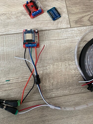
My WS2815 dost not light up … Have you done any specific setup for WLED with the D1 mini/shield ?
The link I gave Is for a ESP32 sorry.
I think this one will work with a esp8266.
I think the ESP32 will be supported more going forward, Its a more powerful device.
I got the esp32 D1 mini for it so if fine, but my led does not fire up. It seems I am missing something.
 Crystal bowl says…nothing
Show us, what you’re doing. In theory the shield should work fine, but there can always be mistakes in putting it together (you wouldn’t want to know how often people accidentally put pins in wrong holes  ).
).
Pictures of how you set that up, and the code from ESPHome (=the yaml code you write in ESPHome, where eg. the WIFI data is, the api and so on). These are the two things to check first. 
Fair enough 
No esp home - flashed with GitHub - atuline/WLED: Control WS2812B RGB LEDs with an ESP8266 over WiFi! latest version (soundReactive_WLED_0.12.0_ESP32.bin).
Changed pin to 16 in WLED setup as suggested on the WLED comunnity for esp32. The standard was 2 that worked out of the box on my esp8266 (without a shield)
I soldered 2 inner rows of male connectors on the D1 mini. I see on the product page, they soldered 2 other rows as well, but I assumed those paralel rows are not connected … !?
… shield schematic here ( I dont understand it tbh :))
https://www.mottramlabs.com/pdf/SCH201123.pdf


