TL;DR — I swapped the OEM Wi-Fi module in my Panasonic ERV for a ~$5 ESP32 running ESPHome, and reverse-engineered its private CN12 protocol. Full local control in Home Assistant + HomeKit — no cloud, no app, no RS485/Modbus gateway.
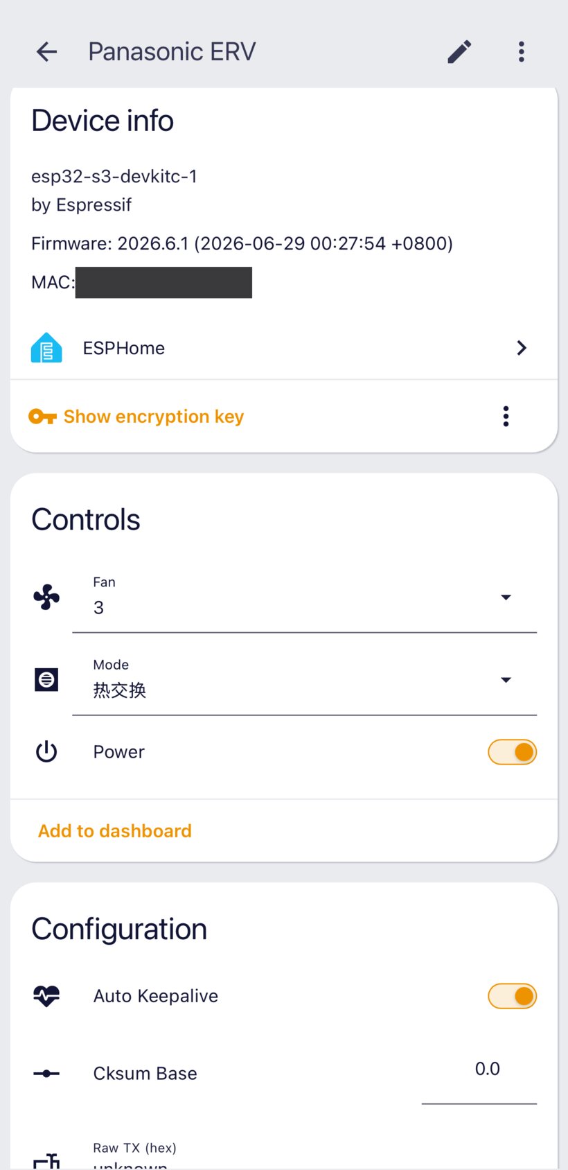
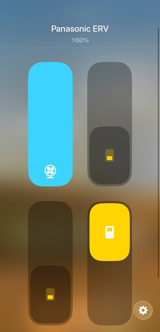
My unit is a Panasonic fresh-air heat exchanger — an ERV (新风 / 全热交换器). Stock, the only ways to control it remotely are Panasonic's Wi-Fi module + cloud app, or an RS485 module on a Modbus setup. Both plug into the same 4-pin header on the main board, marked CN12 — so I dropped the module and put an ESP there instead.
 What you get
 Power, mode (heat-exchange / recirculate / exhaust) and fan (1–3)
 Two-way state — change it at the wall panel, HA updates in ~1 s
 HomeKit out of the box (shows up as a fan with speeds + mode presets)
 Set-and-forget — OTA updates, safe-mode recovery, runs sealed inside the unit
 Cheap, and no OEM module
| Approach | Extra hardware | What you can control |
|---|---|---|
| Smart relays (Shelly / Z-Wave) | a relay or two | on/off + boost only |
| RS485 module + Modbus/TCP gateway | OEM module + a gateway | full, but two extra boxes |
| This — CN12 + ESPHome | just a ~$5 ESP32 | full power / mode / fan, native |
Both CN12 lines are 3.3 V on the board side, so the ESP wires in directly — no level shifter needed.
 How it works (reverse-engineered)
There's no datasheet for CN12, so I worked it out with a logic analyzer. The framing came quickly (9600 8N1, every frame led by A5 A5 5A 5A). The part that fought back was the checksum: a field that changed on every boot looked like an unbreakable per-session nonce — turns out it's a red herring (the board's own status counter). The real command checksum is a plain (Σ payload + 0xC0BA) & 0xFFFF. Building a command with it and watching the unit physically spin up was the payoff.

The full reverse-engineering walk-through (for the curious)
A few evenings with a logic analyzer, roughly in order:
- Find the bus. Pulling the OEM module makes the panel show
F02— so CN12 is the control link and the board expects something there. Its TX line is 3.3 V, so you can listen read-only and safely. - Framing. Confirm the bit width first (an early wrong-baud capture gave me convincing garbage). It's 9600 8N1, every frame led by
A5 A5 5A 5A, then a 2-byte field + a 2-byte message type + a payload. - Message types. The board streams a status frame (
03 0B) every ~2 s; the module sends poll (01 0B) + keepalive (EC 03), a power-up registration handshake, a periodic hello, and a network-time frame. Replaying these at the right cadence is what clearsF02. - State fields. Press power / mode / fan and diff the bytes →
RUN/MODE/FANat fixed offsets. Commands are masked writes (0xFF= leave that field unchanged). - Checksum. Two dead-ends: it's not the AC (CN-CNT) sum-to-zero scheme, and the per-boot-changing field is a red herring (the board's status counter — ignore it). Capture the full 66-byte command frame and the formula falls out:
(Σ payload + 0xC0BA) & 0xFFFF. It matched all three captures, and a hand-built power-on frame started the unit.
The full frame-by-frame spec and the official Modbus register map are in the repo.
 Install
Full wiring, the HomeKit package, and the complete protocol write-up are in the repo. The component itself is one block:
external_components:
  - source: github://shadowzzp/esphome-panasonic-erv@main
    components: [panasonic_erv]
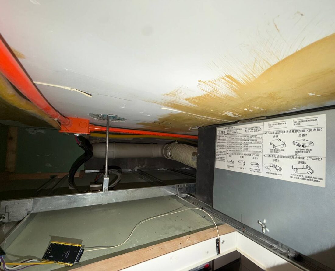
 Will it work on your unit?
Verified end to end on an FY-25ZDP1C (a thin domestic ERV). The same OEM module covers a whole range of Panasonic FY-* ERVs, so they should work too — I just can't test them all, and the modes vary a bit by model. If you have one, I'd love a "works as-is / needed change X" report; there's a tiny dependency-free decode.py helper and the full spec in the repo to make adapting it easy.
Issues, PRs and model reports all very welcome. Hope it saves someone the reverse-engineering!