Looking for a switch/relay that detects 12v => to a sensor

Hi,
i have a doorbell, when someone rings, it triggers 12v dc , 300ma , according to screenshot below
so i can make my doorbell smart :slight_smile: yey
But i dont have experience with electronical componens, but on this forum i see lots of posts about SonOff wifi components? is that someghing i can use? or is there some other kind of switch
so when someone rings, i can intercept that 12v with a component, i read the state of the component, so its like on/off …
component can be wifi, but i am also running Deconz/Conbee, so maybe a battery powered switch is also ok for me?

thnx for suggestions

You could create a voltage divider and have that used as an input for e.g. a D1 mini.
You would create this divider parallel over your bell.

Thanks in advance, this is all new to me, but why do i need a voltage divider?

I buy a d1 mini, I power it with micro USB, then connect the two wires on input pins? So if someone rings, I have 12 v on input, then it’s “on”

Isn’t it as simple as that?

'cause 12V will probably kill the D1 mini that only accept 5V max ?

the inputs on the D1 will only be happy with no more than 3.3V

Use this as a guide:

(http://www.ohmslawcalculator.com/voltage-divider-calculator)

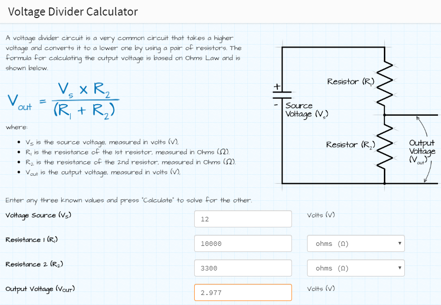
I inserted some figures to help you. The ‘voltage source’ is to be what is coming from your doorbell, connect the ‘output’ to the input of a D1 mini. Ensure the grounds are linked

Ow ok, for you guys it looks easy, seems I need some more components :wink:
I though, I buy something like sonoff, and good to go… :wink:

Ok, thnx in advance, need to read some stuff now

A D1 mini flashed with ESPhome will be easy and better than a Sonoff. All you need is a 5Vdc power supply (micro USB) and a couple of resistors as per my image above. (and a lot cheaper!)

ok, thnx gonna google now :slight_smile:
do you also have somekind of image how the end results should look like? i am quite new to lthose boards and resistors, if its not too difficult,i will try

ok, thnx , that doesnt look difficult, really appreciate the image, thnx!!

The only thing I didn’t draw in is the micro USB power to the D1 mini but you get the idea

Yeah, I noticed that :wink:

Btw, if I want to test without the 12 v dc, just with va regular 3,3-5v dc, I don’t need the resistors, right?

Correct, you can run a wire from the 3.3V pin to an input. Don’t use 5v, it will cook it

ok, gonna order 2 and to some testing :slight_smile:
appreciate the info

thnx

For an easier way, look here :slight_smile:

ok, looks interesting, although i dont see if it also captures a 12v dc

can i also use your same schematic with resistors, but instead the wemos d1 , use a rasperri pi ?
i can then use the PI, also to connect the USB camera from my intercom

and to make it easy, i buy something like this :

You will still need to use 2 resistors to bring the 12v down to 5v