ok, hooked up, confgured like below
no wires, transistors yet on the breadbord, just want to test it
so i can wire from a 3v3 pin to d7 , that should trigger my binary sensor right? but i also need to connect the gnd pins? how can i quickly test from the board ,
so 3v3 pin to D7 , and the gnd ?
thnx a lot for your help, my smart doorbell is up and running stable for 20 days, with that esp 8266 chip!!
now i have a rasperry for testing purposes, cause i was also cable to capture the camera feed with the USB from raspberry, so basicly i want to ditch the esp8266 for now
so with code below and the remote gpio i also created a binary sensor, its also default pull up
when i ring the door, the sensors goes from on to off , working the same as the esp8266
BUT
seems its not always triggering … first 5 times it works, then it stops it seems , so for now i am using the esp 8266 …
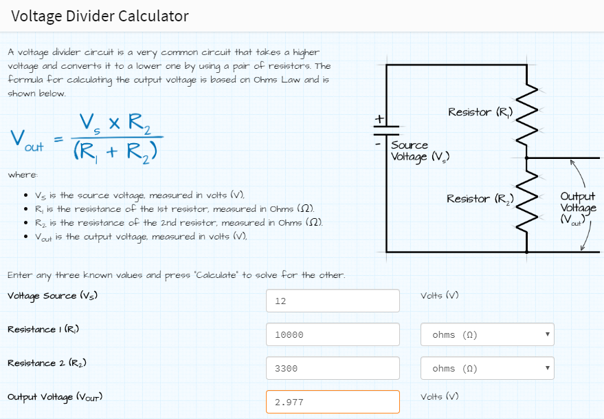
is it maybe because only 3.0 V ? because you choose the resistors 10 kohm and 3.3 kohm to convert 12.0 V to 3.0 v ?
then i replace the 3.3 resistor with a 3.8 resistor?
Fabio, please be careful tagging people like that, some consider it spamming. Taras (for example) has blacklisted them for it.
Regarding using gpio on an HA pi machine please read the following thread including both links from Tom_l : -
There is a known problem.
Edit: but I now see you are part of another thread discussing this very issue. If you manage to get a solution, @Misiu for one, would appreciate it.
yeah, i saw that thread also , but thats another component , they are using a PI with HA on , so local
also that threat is for a quick change, my change is like 1-2 sec, thats more then a quick change i thin, they are talking about less then 1 sec …, mine is more
i am using the remote gpio … stange thing is that it works a few times , when i test, but after a while , like 15 min, if i do the test again, i dont see the binary sensor changing anymore , so disabled it then, no further testing done at that point
Fabio, I don’t mind the tagging some others do, dunno why
According to the pi docs anything above 2.7v as an input is a sure lock.
So 3.0 should be more than adequate.
You did connect the grounds together didn’t you?
Not sure why it would ‘sometimes’ and sometimes not.
Remind me do you still need the 12v ie does it also ring the bell ?
I bet your wife is happy that it sometimes doesn’t work if not ()
If no bell, you could ditch the 12v, use a defence resistor (I’m paranoid) set the gpio to pull itself up and use the bell button just to short it to earth. Though SOMEBODY must have tried that before.
It’s a puzzle, good luck solving it
what do you mean by : connect the grounds together?
if you look in image below, indeed the the cable below from resitor r2 goes to a groudpin on the RPI
the bell still rings inside, thats normal , that still works offcourse, but on my intercom indoor, with the digitall bell, on that intercom is an option to configure an EXTRA doorbell, that i dont have/need, so its my inside intercom, that gives 1-2 sec 12 v on an output GPIO pin, those outputs are then routed to my gpio pins (with resistor schema) to my gpio of the rpi …
the first photo below, where you see the sw+, sw-,extring, gnd, video, those are also gpio pins,i am using those with an UTP cable back to the place where i have my raspberry
with that video cable i am also able to capture the video feed , also connected to my raspberry
I simply mean that if you look at your voltage divider circuit, you have a source voltage and the output voltage from the divider. In the picture it shows that they are both referenced from a common ground, implicit in that is that the grounds are connected together.
It’s kinda obvious, but I’m checking because you once said that when the bell button was not pressed the voltage went to (I think) -2.7v (or abouts)
Just checking is all
yes, indeed with a multimeter directly on the output pins from my intercom, is was like -2.7v, really strange
but on esphome it works … gonna try again with rpi
guide from @frenck is great
If I have a 12V power source and 12V as the signal I want to read, can I use the ESP-01S itself by connecting the power and signal through a voltage devider?
forgive me, but my painting skills are negligible
something like this:


 )
)