Lunos RA 15-60 controlling via ESPHome

I was searching for ventilation fans and I came across Lunos. I like the equipment/attachments they have esp. the different foam inlays look promising to me. Compared to brands like Siegenia – they come pretty naked…

I don’t want to have any heat exchanger fans, so basically 2 fan models are of interest:

  • AB 30/60 (runs with AC, not sure if suitable for esp32 projects…)

  • RA 15-60 (12V DC, I also like these star cut foam noise cancelling parts…)

So I bought a RA 15-60 to play around.

I want to use the fans for both exhaust mode (push air from inside to outside) and as supply air fan (reverse direction).
The RA 15-60 is labelled as an exhaust air fan only, but I try to run them the opposite way as supply air as well by changing the arrangement of the foam inlays I guess, but that’s something I think about later.

The fan can be connected by 3 wires, red “+”, blue “–“ and violet “signal”.
Basically you normally would need a controller like a 5/UNI-FT or SC to run and control the fan, but I want to omit that and control the fan directly with ESPHome/HA.
I’m only interested in turn on/turn off the fan and controlling the speed lvl to use in HA automation in combination with e.g. separate humidity, temperature and what ever sensors…

What I have at the moment:

  • 12V DC power supply to drive the fan

  • A 6-36V to 3.3V DC/DC converter powered by 12V supply to drive the esp8266 d1 mini

  • A MOSFET modul D4184 between power supply and fan, as kind of volt balancer.
    Without the MOSFET, when turning on the fan, there is a huge voltage drop and voltage goes down to ~ 5V what is under the spec of the DC/DC converter and therefore the esp8266 lose its power…

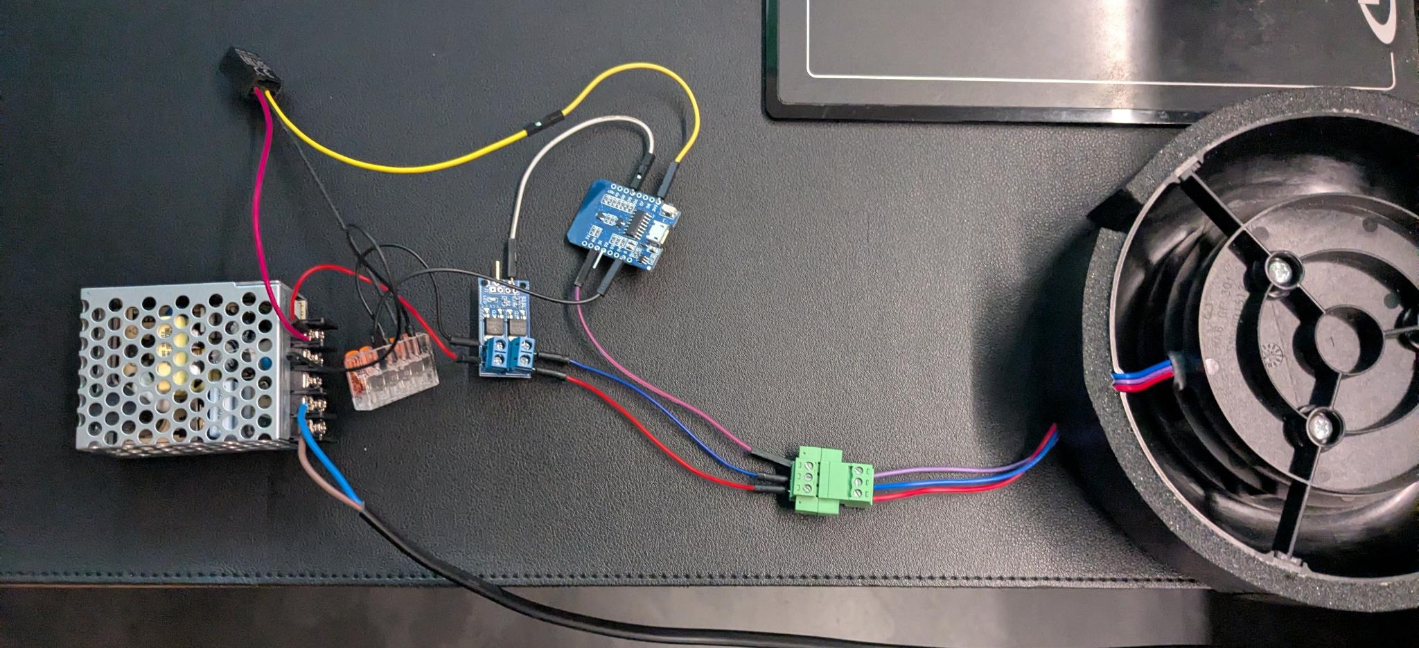
Here is a picture of the test setup:

The behaviour of the fan is that even with connected 12 V to red and blue, the fan is not spinning at all. You have to provide a voltage between 0-10V in order to run the fan.
So in my actual setup, I just connected the violet signal wire with an GPIO (D1) of the esp8266 that is configured as PWM via ESPHome fan speed component.

Here is the ESPHome code:

switch:
  - platform: gpio
    pin: GPIO14 #D5 turn on MOSFET
    name: "Test switch Fan ON OFF"

output:
  - platform: esp8266_pwm
    id: fan_speed
    pin: GPIO05 #D1
    frequency: 1000Hz
    min_power: 0.25 # It seems fan need at least ~0.9v to turn on
    max_power: 1 # 100% PWM singal at 3.3v
    zero_means_zero: True

fan:
  - platform: speed
    output: fan_speed
    name: "Fan Schlafzimmer"

This works quite good. I can control the fan speed and at full 100% PWM (3.3v) the fan spins quite fast.

Based on the information in another thread, @haavhaal gave me some further insides about the fan, thanks again :muscle:
He was able to provide me the voltage range by the signal wire of 0-10V. I’m not sure how fast the fan will spin at 10V, as even 3.3v seems even quite fast. So I could imagine to provide a maximum 5v to signal wire as even higher spin I would not need I guess…

I tried to power the signal wire with up to 4v with an external laboratory power supply and I can confirm the spin feels like even higher as with 3.3v. I was afraid to put more power to signal as at the time of testing I didn’t had the info of 0-10V range…

So now my further questions about the setup and improvements:

I would like to have the possibility to run the fan with a higher PWM signal voltage.
Actually the esp is limited to 3.3v. What I have found so far in the internet is to use a so called logic level shifter to transform the 0-3.3v PWM of the GPIO to a 0-5v PWM.

Is that possible? Are there other ways to do that?

Also, are there other possibilities for the MOSFET or better ways to avoid the voltage drop when turning on the fan?

For me it’s important to use a setup that is as small as possible as I would like to place the electrical components into the fans 160mm pipe by leaving out 1 piece of foam inlay. I think I can easily skip one inlay, as I would use LUNOtherm facade element instead of a normal outlet and this helps even more with noise cancelling.

Pls feel free to provide any kind of improvements. I’m quite a noob in electronic but with ESPHome I did al lot of things like temperature sensor for the gas heating monitoring, or a binary sensor to read a signal of a reed switch to control an extractor hood in the kitchen to be powered only if the window is open… So I have an understand of ESPHome HA and how to configure stuff and things, but when and how to use a e.g. resistor, mosfet, transistor … I’m totally blank xD

So thanks for your comments & cheers,

Hans

D4184 id N-channel mosfet, to my opinion it’s not great idea to cut gnd from 3-wire fan. Quite likely inrush current is less than 2A so if your PSU can’t handle that, it’s underrated or crap.
If you are confident that the correct control method is analog 0-10V, you need DAC. Esp32 has, but then you need to amplify it.
On the other hand if your experiments show that it works with PWM without hiccups, use that and shift it to 5V with npn transistor.

Make a voltage divider or use potentiometer and experiment how it behaves with different analog voltage levels.

Hello again, Hans

The voltage values I posted in the other topic is noe relevant/correct when connecting and controlling the fan like you do. Those values are input values for Lunos’ own control units, and not the actual output that control the fan speed.
I’ll measure and post those values for you, but I’m not able to do it today.

Regarding signal and protocol; in order to get the fan spinning correctly you’ll need to use a 0-10V current sourcing signal. PWM and 0-10V current sinking does not work properly.

Shelly 0/1-10V PM GEN3 will do the trick, but you are free to use anything that can provide the right signal as long as it doesn’t fluctuate too much.

I’ll get back to you with the exact values we use on our controller tomorrow or the day after tomorrow. Please PM me if I haven’t posted anything by the end of the week :see_no_evil:

Hi @Karosm the power supply is a meanwell, thought this wouldn’t be a crapy one…

Hi @haavhaal, thanks again for replying on my thread :smiley:.

So using the Shelly is for the purple signal wire only right? I would need a separat 12V supply for the fan in addition right?

How would the wiring look like, Shelly V+ to purple fan wire, Shelly V- to fan blue wire :person_shrugging: or ground?

Keeping the esp32 setup, would a DAC be an alternative for the 0-10V signal?

Then it’s underrated. And while meanwell is good chinese brand, there might be fakes around as well.
If haavhaal confirms that the fan itself (not the control board) takes analog 0-10V, you can go with Shelly but be aware you need Gen3.
Otherwise go with esp32 dac and amplify that or get some cheap “PWM to 0-10V” module from AE, they are powered at 12V.

@Hans22
here are the output voltage from Lunos’ SC-RF when it’s set up to control the RA 15-60.

RA 15-60
LEVEL VOLTAGE HA % input
1 1,6 16
2 3,5 35
3 5,7 57
4 8,1 81

The HA % input levels has to be adjusted so that the actual voltage output from the DAC/Shelly is correct.
The 0–10 V input is used more like a “multi-level selector” than a true analog speed control.
If you use the Shelly mentioned above you’ll also need a 12VDC power supply as you mention yourself. just make sure to connect both GND from the power supply and from the 0-10V output from the shelly. both “positives” need their reference points

1 Like
Wiring diagram – RA 15-60 with external 12 V PSU and 0–10 V controller


    12 V PSU                                   Shelly / DAC                    RA 15-60
┌───────────────┐                           ┌───────────────┐               ┌───────────────┐
│ +12V ─────────┼──────────────────────────────────────────────────────────►│ +12V          │
│               │                           │               │               │               │
│ GND  ─────────┼──────────────┬───────────►│ GND           │──────────────►│ GND           │
└───────────────┘              │            │               │               │               │
                               │            │ 0–10V OUT ───────────────────►│ 0–10V         │
                               │            └───────────────┘               └───────────────┘
                               │
                               └──── Common ground / shared reference
1 Like

Many thanks for your replies!
@haavhaal what you mean exactly with HA%?
Homeassistant percentage for e.g. the fan speed component analog slider?

If I remember correctly, the SC-RF provides 4 fan speed level and your table represents them.
But I guess it is also possible to control the fan with any other voltage level in between (e.g 6.6v) right?

I modified my initial setup to use the internal DAC (3.3v) of the esp32 board.
With this setup there are no voltage drops anymore, so it really seems the fan does not like PWM and needs to be driven with an analog voltage signal!

I now ordered a DAC GP8403 to play around. ESPHome has an output component for this DAC, so my hope is for easy usage :slight_smile:

I keep you updated…

HA% is maybe not the best way to put it. What I meant was that 0-10V will have to be converted to 0-100% if you use a 0-10V controller/dimmer like Shelly.
However, and this is important, in order to get it right you need to use a multimeter to measure the output of the 0-10V controller dimmer. Shelly’s default dimmerprofile is not 100% linear så 48% input i HA might be 4,2V. This is just an example, but I recommend measuring to get it right.
Regarding voltage values and ventilation levels. This kind of 0-10V controlled fan/engine is not really linear. It’s setup more like “voltage-windows values” that typically are 0.5-1V. In other words; the value for level 2 that I listed as 3,5V will have a working window of +/-0,5V. So 3,3V will definitely be within that window. 6,6V however is not within these the window of any of these 4 levels, so I recommend using somewhere between 5,4-6,0V.

On a sidenote; Lunos e² 60 ventilator has 16 voltage windows when a 0-10V controller/dimmer is connected to the 0-10V input on SC-RF/FT or UNI-RF/FT. However, there are much fewer voltage windows on their output to the ventilators.
:wink: